• Please review our updated Terms and Rules here

Identifying capacitors on TEAC floppy controller board

GearTechWolf

Experienced Member
Joined
Apr 24, 2015
Messages
264
Location
Washington
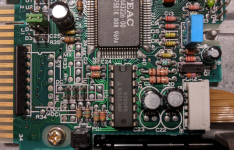
Main-board from a TEAC FD-55GFR. The two capacitors (C25 + C23) in the driver-circuit for the stepper that drives the head, are they non-polarized or just not labeled with clear polarization? (the silk-screening doesn't show any indication of polarization either)
Related question: Is the stepper driven by AC or DC? If the former, then I'd expect those capacitors to be non-polarized.
I'm working to repair some boards that got damp and these caps got corroded/lumpy.
Are they electrolytic? If so the polarization should be marked. Also, if they are electrolytic, there's a decent chance one side connects directly to the ground of the drive's supply. Not always, but that is one way to check. Or are they SMT ceramic? Those aren't polarized. No ceramic is.

If the stepper is driven by AC or DC is a trick question. It is driven by DC pulses, which may or may not change polarity depending on the configuration. Do you have a picture? I see VeryVon's picture but can't find C25.

Another way to determine this is find the datasheet, if you can, of the chip they are connected to.
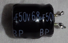
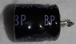
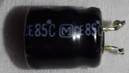
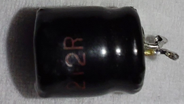
Yes, electrolytic. Non-polarized electrolytics do exist. Polarization isn't marked unless BP stands for something.
(bi-polar? Would that equate to being non-polarized?) Already checked against ground, no direct connections.
Ah, I thought that might be the case. The equivalents in VeryVon's pic are C21 and C20, although their board uses a different stepper-driver IC.
BA13002F, found the datasheet, Darlington transistor array, but the example application circuit lacks any capacitors at all. Ditto on M54534P.
Haven't been able to find a datasheet for the main IC on the controller-board, 2207-00 IR4N10.
I wonder if I could replace them with two polarized caps in paralell, one facing each way so there's always one going the right way?
I suspect the frequent applications of reverse-polarity would lead to quick failure if I did that.
A diode in series with each cap might mitigate that, but by that point it would be cheaper and easier to buy replacement capacitors.
I could attempt replacing with ceramic caps but I suspect I'd still have to buy some in order to get a matching capacity of 6.8uF at 50V or more.
I didn't expect to find such components on this board, a curious challenge to repairs.
 
I wonder if I could replace them with two polarized caps in paralell, one facing each way so there's always one going the right way?
No. In parallel one will always be reversed biased and break down. Bi-polar caps are two caps of twice the capacitance desired in series with polarity reversed.

Mouser uses bi-polar and non-polar interchangeably. Official bi-polar work better than two in series since mismatch between capacitors can cause issues.
https://www.mouser.com/c/passive-co...ct=Bi-Polar/Non-Polar Electrolytic Capacitors
 
Yes, electrolytic. Non-polarized electrolytics do exist. Polarization isn't marked unless BP stands for something.
(bi-polar? Would that equate to being non-polarized?) Already checked against ground, no direct connections.
Ah, I thought that might be the case. The equivalents in VeryVon's pic are C21 and C20, although their board uses a different stepper-driver IC.
BA13002F, found the datasheet, Darlington transistor array, but the example application circuit lacks any capacitors at all. Ditto on M54534P.
Haven't been able to find a datasheet for the main IC on the controller-board, 2207-00 IR4N10.
I wonder if I could replace them with two polarized caps in paralell, one facing each way so there's always one going the right way?
I suspect the frequent applications of reverse-polarity would lead to quick failure if I did that.
A diode in series with each cap might mitigate that, but by that point it would be cheaper and easier to buy replacement capacitors.
I could attempt replacing with ceramic caps but I suspect I'd still have to buy some in order to get a matching capacity of 6.8uF at 50V or more.
I didn't expect to find such components on this board, a curious challenge to repairs.
I know there are non-polarized electrolytics, I have a few in my stash. I've seen "NP" for "no polarity", but BP....I don't know if there's a standard for that. Could be bi-polar as you said. Every electrolytic known to be polarized I have seen in the last few decades has been marked. So if there's no markings, it's fairly safe to say they are non-polarized.

Ok so the driver IC is a standard Darlington array. I wouldn't expect much help from the datasheet in that case, but it does give a clue about the outputs. You wouldn't want to put two polarized caps in parallel because one will always be reversed, and they don't like that, as you pointed out.

And I just decided to look for NP caps on Digikey and aha! BP is indeed marked for this purpose. I use so few NP caps I rarely run into this. Here's an example but I found others in my search results that also had the B.P. marking: https://www.digikey.com/en/products/detail/nichicon/UVP1C332MHD/2539561

You could use a diode on each polarized cap in parallel, but I'd avoid that. The voltage drop of the diode and some non-linearity could screw things up. Not to mention that you now have two capacitors masquerading as one, so that would be, uh, interesting. My advice is to get the correct replacement and save yourself headaches later.
 
We are assuming that the capacitors are bad and you are not just shot gunning the board. I would check them before just replacing them.
Any board can be fixed if you replace everything, including the board.
Dwight
 
Yeah, that clears that up then. They're non-polarized. I won't be trying a janky caps/diodes kludge.
Film caps, eh? I've got a number of those, I'll have to see if any are close enough in value. Probably have the room.
I'm assuming they're bad because one had a leg corroded entirely away and the other has holes corroded through the casing underneath the label.
But thanks for making sure I wasn't replacing things willy-nilly! One of these boards could use a dip in evaporust to clean the resistors and resistor-arrays, though I'm not sure whether it would eat the semi-corroded solder and make everything fall off the board...
Wow, Mouser is back-ordered until March at the earliest! Good thing this is just a side-project to see how many of these corroded drives I can restore.
 
Last edited:
I've seen very old ceramic caps that look like that, in old radios. Yeah, they are nonpolarized. I would think if you can find a disc capacitor of the same value, it would fit nicely and work fine.
 
I've seen very old ceramic caps that look like that, in old radios. Yeah, they are nonpolarized. I would think if you can find a disc capacitor of the same value, it would fit nicely and work fine.
Right you are! I found a couple disc-caps of the right capacity, although being 1KV is a bit overkill, they should work.
Sadly, none of my film-caps were high enough capacity.
 
Here they are installed! Testing will have to wait until I have a computer that can interface with 5-1/4 drives operational, unless there are jumper-settings to make it run a self-check once it's installed in a stand-alone drive?
 

Attachments

  • 5inchTEACfloppy-1.png
    5inchTEACfloppy-1.png
    1.5 MB · Views: 11
Aw nuts. Looks like I'd need ones labeled 685, instead! Well shoot, I don't think I have any suitable caps in my parts-drawers then. That sucks!
Still, thank you for pointing that out before I hooked this up to power. Dunno if it would hurt anything, but don't want to risk it.
 
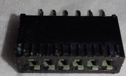
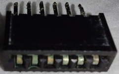
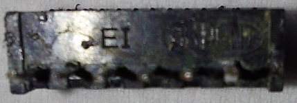
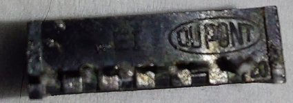
Also, did you know TEAC floppy-drives had parts made by DuPont?
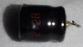
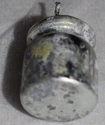
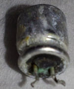
TEACconector-1.pngTEACconector-2.pngTEACconector-3.pngTEACconector-4.png
This is the connector on the underside of the main-board, the one that goes to the board that has the activity light and the top half of the optical disc-detection photo-diodes.
 
You can do the back to back capacitors of twice the value. Since these are for the stepper, you can test it with some wires and a switch. You don't need a computer to test the stepping.
You'll need the edge connector, the power connector and a power supply.
Look at the spec sheet. You just need to set the select the drive enable pin. Then you can put one switch on the direction pin and one on the step.
Dwight
 
Back
Top