• Please review our updated Terms and Rules here

Looking for a datasheet DEC T11 Cpu

GilesGoat

Experienced Member
Joined
Dec 11, 2010
Messages
138
Location
Wales
Hi,

I stumbled across a DEC T11 CPU ( 10 Mhz I suppose ) which is actually on a board of a "Championship Sprint" Atari videogame.

I was trying to find out some datasheet of it, any idea where I could find any ?

It would be tempting to use it to build something small computer with it.

Thanks in advance for any help, I did try to search the internet a bit there and there but found nothing yet.
 
Hey thanks that's really great !

I downloaded the 2 documents and had a quick look seems pretty good.

Completely forgot about Bitsavers, that's a great place.
 
That manual is a pretty good read. Let us know how you like it.
 
OK I've been reading it for quite a while, you are right, it should be more than enough to build up something :)

A couple of very silly questions .. actaully more than 2 ..

What really impresses me ( never seen this CPU before ) is "how much it looks" like a Motorola 68K ( actually I read the 68K took inspiration from the PDP architecture ).

In fact it looks a bit like a 16 bits 68K with no supervisor mode and a bit less instruction but wow .. even mnemonics are quite similar.

So is it the address space really limited to 64K ?

I/O I suppose it's memory mapped ? Can't see any dedicated IN/OUT instructions.

Suppose I make a small board with 64K static ram, some "bootstrap rom" ( maybe mapped over some address space that then can be switched back into ram again ), some UART and maybe an IDE interface to connect a disk ..

Could something like that run RSX-11 or such ? Or the CPU itself is "too cut out" to run RSX-11 ?

Even without the above ( ok I do have a PDP-11/something emulator running with RSX-11 I maybe could use for that ) are there around any PC runnable ( or such ) assemblers capable to assemble T1 code ?

I think it's a really interesting CPU with interesting features, first time I see a CPU that has directly support for dynamic rams, like that story of the "mode register".

[edit] - sorry I meant RT-11
 
OK I've been reading it for quite a while, you are right, it should be more than enough to build up something :)

A couple of very silly questions .. actaully more than 2 ..

First, it seems I need to correct myself... I originally posted the wrong description for those two documents.

  • T11_UsersMan.pdf Is EK-DCT11-UG-003 This is the "Microprocessor User Guide" and is sufficient to design hardware. This is what I intended to direct you to.

  • EK-DCTEM-UG-001.pdf Is EK-DCTEM-UG-001 and is the "Evaluation Module User's Guide" and helps one use the DEC supplied T11 Example Design Board most designers start with.
From your comments, I think you already found your way to the Microprocessor User Guide. I must have fallen asleep 5 times before I managed to get through that manual [EK-DCT11-UG] the first time.

The DCT11 ["T11" as we call it] is a great chip for it's time. If it had been executed in CMOS it would have taken over the industry, and been competitive with the Z80.

As you note, the 68K line borrowed a lot from the PDP-11. In fact, as I understand it, NATIONAL actually implemented a PDP-11 clone, which DEC immediately went into litigation over and stopped. I suspect, Motorola took notice, and changed it's designs just enough to keep from becoming embroiled in the same kind of issue themselves.

The T11 was never intended to be a full fledged PDP-11 family member. I understand it was an almost orphaned project at DEC, stopped and re-started more than once. Since it was targeted specifically at "Embedded Systems" it was thought the 64KB limit would not pose a problem. [Remember the cost of memory was such that this was really a good decision for many years, even after the delays]

The instruction set is missing some things other PDP family members have, such as integer MULtiply/DIVide instructions, but it does implement the MTPS model of non-memory mapped processor registers and status words. It's kind of an in-between child in some respects. Appendix B gives a good summary. It's pretty much like an 11/03 or 11/23 without Memory Management.

I/O is memory mapped. However, you put it where you want. The CPU doesn't know it any different than any other "Memory Register". DEC tradition has this in High memory.

As for a "monitor"... I have translated Paper Tape ODTX to a version compatible with the T11, and to run on an 8-bit bus that other [totally different] CPUs were designed for. I feel it's versatility to adapt was unmatched until the 80386EX, in my experience.

OS Compatibility is not something I can answer off the top of my head. I'd be surprised if it couldn't run RT-11. It might run a very old RSX, perhaps compiled for an 11/03, but without an MMU and limited to 32KW, I don't think it would be much use.
It is worth noting that there might be very concise answers to this question. I'd look in the manuals for the KXT11-AA and -CA boards. These were capable of being QBUS processors, or co-processors and it seems to me that this question would come up with their application.
That T-11 CPU manual is quite a read. In my designs, I began by copying the manual sections I planned to use, and EDITING OUT the sections that were irrelevant to my particular needs "of the moment". This reduced a very complex document to a simple easy to follow manual. It helped "unclutter" my thinking process, and later made handing the project off to others, a breeze.

I would use this technique often in my later career.

Let us know what you decide to do.
 
Last edited:
DCT11 Evaluation Module

DCT11 Evaluation Module

I thought some would like to see what we've been discussing. This an original DEC DCT11 Evaluation Module - Prototyping Board.

DCTEM_pcb.jpg


This is the usual platform an engineer would get to begin his first T11 based designs.

Many manufacturers make one of these when first introducing a brand new chip. It helps engineers spin-up on product development much faster and more reliably than starting from scratch with only data books to work from.

As it turned out, I received this DCTEM after prototyping my first T11 design. [naturally I kept it as a prize anyway!]

Here are some examples of my prototype wire-wrap designs, and their corresponding first PCB versions.

1805%201854%20DCT11.jpg


The T11 boards are on the right. Center is an enhanced mode 1854 serial interface. On the left is an RCA 1805 capable CPU. All these are designed for the same proprietary bus architecture. I'm pretty sure my co-workers thought I was nuts to put a PDP-11 on this 8-bit bus in 1984, but there you are!
 
Last edited:
I think that the T-11 based pdp-11/21 Falcon could run RT-11. If this is so, then one should be able to make their own T-11 based computer that could run RT-11 (sounds like something Reinhard would do.)

I too have a DCT11-EM: http://www.vintage-computer.com/vcforum/album.php?albumid=54&attachmentid=2551

The manual for the DCT11-EM that is on bitsavers was scanned by Andy S. of down under. I cleaned and straightened the pages and made the .PDF. So now I know of three people with this board.

The DCT11-EM has a little monitor running on it. The original poster could use the rom dumps from the DCT11-EM for his project. I dumped those roms and can pass along a link as to where to find them on the internet. The MACRO-11 listing for those roms is in the back of the manual.

Lou
 
There you have it from the best source. T11 runs RT11...

Coincidence?
 
The manual for the DCT11-EM that is on bitsavers was scanned by Andy S. of down under. I cleaned and straightened the pages and made the .PDF. So now I know of three people with this board.

I too have a DCT11-EM. Actually two of them. The first one was just the board and no manuals. I bought the second one because it came with manuals and I couldn't find the manual anywhere online at the time.

I like to think of it as the T-11 version of the KIM-1.

-Glen
 
Huh .. maybe I should have also mentioned that not very long ago, cause someone was "throwing them away" I managed to grab on Ebay the full original set of the DEC RT-11 Manuals .. it's a big box ..

I had some lecture just now I see the whole system is designed to fit within 28K words or memory ( 56 K ) and reserves the last 8K of memory as "I/O space".

By the sound of it, it also uses disk with 512 bytes ( 256 words ) sectors.

While down the pub ( was a lot of noise ) I was trying to understand something of that board, not clear to me if it's using two UARTS and what is that "DUART" chip E9 mentioned, I'll have to study better the diagram to see in what address space they are mapped, the other chip seems to be an 8251 USART.

I think I have some ideas about what I could do, I am planning for a static 16 bits configuration, something around the lines of cpu, clock, one CPLD, ram and 2x276c64 eeprom + 1 uart of some sort and probably and IDE bus and that would be my "starting point".
 
Ok I wish to add a thing, as this is a quite "unusual" project.

OK first of all "is my hobby", I'll do my best to keep it going but it's going to go "after work hours" so "as slow/fast as it goes" :)

As soon as I'll have something in mind/I'll start making up something I'll put schematics and a little thing about the progress here, remember this is all made "just for fun" and especially "because I'd love to see that chip alive again doing something" and not where it is now, on an Atari II board in a garage getting dust and rot.

Actually I should take out of the garage those boards "before it's too late" and check the chip is ok :)

But yeah, literally I do this stuff "a bit there and there" during week end or after midnight/first hours of the day so "it won't be ultra fast" :)

Ah also I should add :

"I do it all home", I have a "mini lab" but basically "stuff put together during years" mostly I do by "wire wrap and matrix board" ( actually I never done real wire wrap I always solder ) however I do my best to do PCBs but it takes so long time, in the recent times I self-taught myself VHDL and began to use Xilinx CPLDs, I quite like CPLDs, economical and such and still "electronics one can well understand" :)

Never tried FPGAs yet, I have the feeling the can be "too easily abused".

I am the kind of person that tries to embrace the motto "do more with less" and "no gate or transistor should be wasted" or such.

Another reason I love this kind of stuff is "when it was its time I was too young, the things were too expensive, I wasn't able to understand them but now I CAN " :) also, I believe there's really "so much we owe" to all that stuff "we should never let it rot", it's part of our memories/culture/where we are/etc.

Plus "I always wanted to see it working" and now I have a chance to make it work :)

[edit] - the manuals I was talking about :

manuals.jpg
 
Last edited:
I really don't know how today's students / engineers can possibly work from only "electronic" documents.
Unless they're using 5 computer screens simultaneously that is.
Back in the day, absolutely everyone in our facility and my experience, even those with photographic memory, all used DEC systems manuals in the same manner... 3 or more at once.

In order to really be productive, we all learned to use paper clips, dividers and later post-its to organize and annotate our documentation.

Ever hear of MBWA? [Management By Wandering Around]
With an active engineering department, there are always newcomers, and transitory specialists like consultants and contractors. Keeping track of people's status, without making them paranoid or interfering with them is quite an art form.

I remember giving a lesson on this to the V.P. or our division one evening after quit'n time. We simply walked through engineering and toured the various cubicles. Whenever we'd get to the desk / office of someone we knew well, we could see what they were up to, and pretty much evaluate the intensity of their depth into the current project by the evidence of manuals, notes and other paraphernalia scattered throughout their work area.

When we'd get to someone's area who was new, or just starting, it was entirely different. Usually organized, spartan - barely used office spaces meant inactivity or still getting their feet wet.

Whenever we saw a long-timer with a clean empty workspace, we'd check the vacation schedule. If not actually "out of the facility", we knew we should start to worry and look into things.

Of course there was always the occasional exception, but in general this worked very well.
The axiom "Empty Desk - Empty Mind" was coined by one of our engineers who had also noticed this pattern.

You're lucky to have these manuals, especially in their original form. Treasure them, and use them in good health.

Even in these days of electronic indexes and PDF files, I find my old, "hard copy" manuals indispensable. [although it is nice to have electronic search of the PDFs as an adjunct]
 
Re: T11 OS compatibility -

Re: T11 OS compatibility -

I decided to consult these SPD [Software Product Description] to answer this question.

RSX-11M v4.1 (SPD 14.35.22) June 1984 states:
Minimum Hardware Required for System Execution: [not Sysgen]​
  • CPU - Any UNIBUS PDP-11 Processor, PDP-11/23, PDP-11/23 Plus, Micro/PDP-11 or PDP-11/70
  • Memory - 32KB bytes Unmapped [16KB system, 16KB user tasks] , 56KB Mapped [*128KBytes for RA60/80/81 support]
  • DL11 compatible console
  • Clock - KW11, DL11-W if not provided by CPU or bootstrap.

A T11 is an Unmapped System with a maximum address space of 16 bits [64KB] minus I/O

This is further verified by the General License options section:
A "general license" grants the right to use all of the following on a single cpu:
Micro/RSTS, Micro/RSX, RT-11, RSX11-M, RSX-11S, RSX-11M-PLUS, DSM-11, RSTS/E, CTS 300
  • QJB36-UZ DCT11 Microprocessor Chip
  • QJB39-UZ DCF11 Microprocessor Chip
  • QJB43-UZ KDJ11 Microprocessor Chip
  • QJB46-UZ KD11, KDF11 CPU Modules
  • QJB51-UZ 11C23 MICRO/PDP-11 Models and systems
  • QJB56-UZ 11/03 through 11/23 Models and systems
  • QJB66-UZ 11/24 through 11/40 Models and systems
  • QJB76-UZ 11/44 through 11/70 Models and systems

RSX-11M-PLUS v2.1 (SPD 14.70.11) December 1984 states:
Minimum Hardware Required for System Execution: [not Sysgen]
  • Memory - 256KB (This alone precludes the use of a T11)


RT-11 v2C (SPD 12.1.4) December 1975 states:
Minimum Hardware Required:
  • CPU - any PDP-11 [of the 1975 era] but specifically adds PDP-11/03 support
  • Memory - 16KW (32KB) or more for full F/B functionality, limited functionality with 8KW (16KB)


So, in summary - Although I do not have an SPD for RT-11 of a vintage concurrent with the T11, I conclude that RSX-11M v4.1 can indeed be run on a T11 as an "unmapped" system with 32KB or more memory as long as it conforms to other system requirements. I sincerely doubt that DEC would do this and not offer support for the same vintage of RT-11 on a similarly equipped system. Note also that this is the last version of RSX that can support that environment as v4.2 requires a minimum Mapped 192KB system.

I am still looking for an archive of RT-11 SPDs, so those of you out there who have these or know the whereabouts of them, might post here.

UPDATE:


  • I located Mentec's SPD 12.01.41 for the final RT-11 version 5.7 October 1997, and although there are restrictions as to which monitors may be used, Unmapped systems of 32KB for SB, and 48KB for FB were still supported. T11 cpus are not specifically mentioned, but I think that generically these attributes indicate it must work.

  • The User's Guide EK-SBC02-UG-001 for the T11 based SBC-11/21 Plus KXT11-AB "Falcon" [a dual QBUS Single Board Computer module] specifically states it is compatible with RT-11 and that both SJ and FB monitors are supported.
This pretty much settles the question.
 
Last edited:
Hi RSX-11,

thanks for doing all that research :)

About this :

really don't know how today's students / engineers can possibly work from only "electronic" documents.

Unless they're using 5 computer screens simultaneously that is.

I do have 5 screens on this very desk, actually 4 on the desk one fixed on a wood beam of the ceiling using two strips of alluminum :D

I don't know if I am "today" or what ( I consider myself 'those that in 1984 were battling between Commodore 64 and ZX Spectrum ) I am nearly 41 years old, alas I am not really an engineer nor a student but technically I am both "all the time", in this job you never stop studying something new or old :)

Altough must be say the advent of the iPad is something "in terms of portable book one can read and have around" yes I do believe "you'll never replace a paper book" and I do consider in general DEC Manuals like "the best tech documentation ever written that maybe no one else will ever surpass".

I am full of books around me, books are fundamental.

When I was working before in a certain company ( those were good times ) there wasn't much to wander around literally because the place was really small but we had a lot of talking and sometime we had ( kind of "a must" being in Italy ) the "espresso engineering walk", because literally given so small the place was that was the only way to have a real 5 minutes walk.

I don't know if MBWA includes stuff like my ( ex ) boss coming while I was writing code and asking me "How's going ? .. Ah good good .. Aaah that's good go on .. " .. and 25 mins later repeating the same identical procedure/questions for about 5 .. 6 times a day ..

I admit I never heard that "empty desk, empty mind", well I could say - really - I NEVER managed to have an empty desk, actually my desk ( even now ) always been full "of everything", the only times I've been forced to empty it ( but did not last more than 1 day ) was when "someone important" were coming to visit the place and they wanted to give the place "that look" I don't know ..

Ultimately they actually realised that "in case someone was visiting the lab it was actually better to show it for what it was" .. a place full of really full desks ..

Well .. as I said "to being with", I think that a static 16 bits configuration could be a start, there are a few issues to consider/understand.

First of all it seems to me "it's kinda a standard" that the lask 4K words of memory is the I/O space, I have to study the documents to see if I can actually understand at least "more or less" where they want what even if, using the HW "of today" it will mean someway I'll have to write at least the serial port driver my own, I mean even if I'd map my UART chip at the same I/O address I don't think there's any chance the SW would work straigh on being the chip totally different.

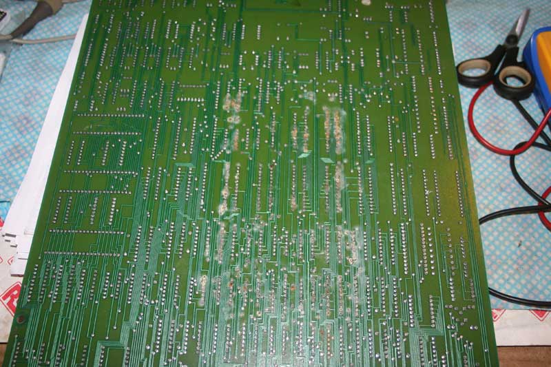
About memory turns out I have a couple of chips around, I could actaully build "something incredibly simple" ( i.e. I have 2x32K ram and 2x8K roms ) or even less ram, I have some 8K chips around, really "clock ram rom and maybe that SPI uart I have around" to literally "test the chip".

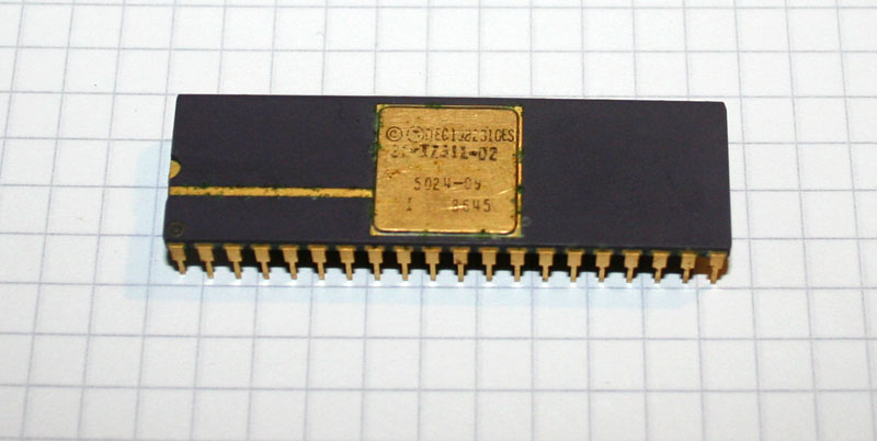
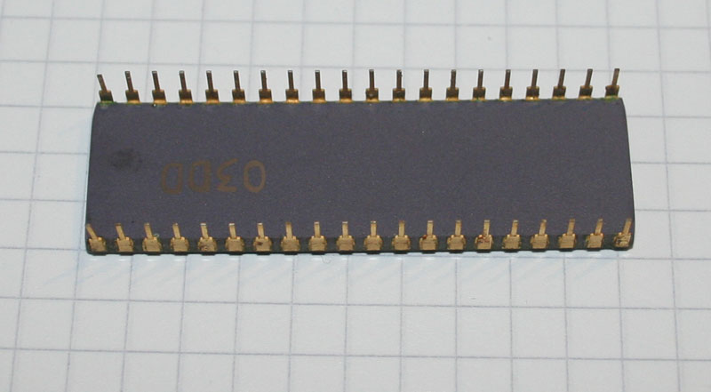
That chip I have around I really don't know ( yet, but it should ) if it works, before to go "too deep" I think a "let's see if it works" is imperative, if it would turn out that chip does not work it's all over.

I could do some really simple code like "start, output some counting on a display and stay there in loop", I even have a beatyful TIL 31 laying around that just to see if the CPU is working, if I understood correctly the start/restart address is got from the "mode register" ( 4.2.5 of the manual ) so "ram at 0000", "rom starting at some high address" and you are good to go.

Yes I think I should start with a "CPU tester" then I can move from there once I learnt a thing or two about it :)
 
I just wish to say I finally found a full schematic of that board and yep .. totally and definitely is a T-11 cpu, I think I should get those boards in to save them from the garage now ..

A pic here, you can see the T-11 and the mode "register".

Cpu_Detail.tif

Interesting I am seeing they are using a tecnique similar to one on the ZX to stretch the clock to "freeze/slow" the cpu, it seems to be using the to solve the bus conention problem between the CPU and the video stuff.

Anyway I a going to save two boards from a garage.
 
T-11 Tester eh?


You know... there is a "Test Mode" built into the chip. I've never seen anything on what it does. All the documentation I've seen just says "DEC Engineering Only" or words to that effect.

Let me look around.... building a self-test fixture for the chip may be simpler than one would think.

Also...


  • would you please publish the remainder of that schematic? I'd like to look at it.

  • On MBWA... Doing it without interfering is the "art form" part. What I was demonstrating on the walk I described was after everyone had gone home on a Friday. We were touring an empty department so there was no one to be bothered. [It sounds like your boss never got that demo;)]

  • Books vs Electronic Readers - I'm not advocating giving up either one. Both have their strengths. I just don't know how students today can cope... I don't think books are going to be around much longer. It makes me afraid, if not for this generation - certainly for the next.

  • A word about the console serial port... I am sure a CPLD could be programmed to imitate one, [there might already be a program available] but I don't think it's necessary to imitate one exactly. I believe [for most systems] it only needs 3, byte-wide memory registers. TX data, RX data, and a status register with two bits in the correct place. [Data Available [DA] and Transmit Shift Register Empty [TSRE]. I think everything else can be faked and hard-wired. It should be possible to do it with a common UART and a little logic. [Where does one get a "Common UART" any more?? LOL]
 
Last edited:
I had to dismount the whole cabinet door, the two boards ( CPU + video ) are big and joined together by a connector, there were a number of cobwebs and such.

It took quite a battle just to remove the door and use of some lubricant for very rusty bolts and nuts.

I managed to have all in a vacuum all out and remove all the dust and stuff.

After more carefulness and better tools ( and the fact I was able to work finally indoors ) I managed to remove and separate the two boards.

The video board seems quite ok, the CPU board unfortunately had more damage underneat, the problem is they put some kind of "foam pad" surely to protect the PCBs from flapping around, this by years absorbed water and such and created "a patch of oxide and rot" under the PCB.

Anyway the CPU was on socket and the area underneat it was ok, thanks also to the gold plated contacts I think it's ok, I very very carefully removed it from the socket, I was so scared cause it's ceramic and the socket was really old.

Pics, you'll see what I mean :

The sponge pad

T11-1.jpg


The cpu recovered from the board, top

T11-2.jpg


And Bottom

T11-3.jpg


The damage caused by the rot ( after quite some cleaning, it was a real mess before )

T11-4.jpg


The board where all this is coming from, that spent about .. boh .. 6 years for sure in not exactly good weather/room conditions ( actually I am amazed rats did not eat it ) ..

T11-5.jpg


That 40 pins empty socket you see in the bottom close to that connector that is where the CPU was, those other empty sockets were just empty.

I do have the feeling that "with some proper cleaning" probably everything could work, maybe the ROMs could have problems but I am NOT going to try to power that PCB until it would be really properly cleaned and checked.

If that CPU could work again that would be "score" ;)
 
LOL - It hurts me to see that board get torn up after so long... you sure it's not worth something??

Whatever...

You might have all the "parts" you need there. Actually, you might be able to run RT-11 on that board!

Post those schematics and we'll look. A couple hi-res photos of the board will help too.

P.S. - I added to my previous post, so please note the changes.

Ok first of all I am *NOT* going to destroy that board, actually I am trying to save it, the reason I took if off that door is to give it a place inside the house where I can keep care of it, by time, I'll try to clean it up and see if it can be powered up again.

About the diagram I downloaded it from here, it's a PDF.

http://arcarc.xmission.com/PDF_Arcade_Atari_Kee/Paperboy/Paperboy_SP-275_1st_Printing.pdf

If that board would be not so damaged by oxidation I could connect a PSU and try to see what happens but as it is I need to be sure it's well cleaned and probably some solderings will need to be re-done.

I use CPLDs just, possibly, "to have N chips into one", they are great to replace N chips of glue logic/decoding/etc. into a single one .. yet normally the problem is "you don't have enough pins for everything".

One "trick" I found out and I used it a few times it's relatively easy to create an IN/OUT SPI port using the CPLD, then I can connect an SPI uart like the MAX3100 for example to it.

Otherwise I was thinking in adapting some Z80 DART/SIO I have around here.

I think you'll find the PDF more useful than the high-res photos, the board is actually a CPU board + a video board but it also has a protection chip ( that don't know exactly how it works ) so it may be all the roms gets chipered/scrabled or dunno what ( Atari SLAPSTICK chip ).

I guess you could probably hack that board and transform it into a computer or such, a quite strange one :D

[edit] - ah that board in reality is "Championship Sprint" not "Paperboy" but the difference is mostly in the ROMs, the board is the "Atari System 2" which is a "standard board" made by Atari that could have been used/"transformed" into other videogames ( by changing the SW ), it has quite some stuff the only missing thing to make it "a computer" is really an UART.

But a quick look at the memory map seems to show that, if we exclude the video/colour ram there are only 4K of program memory available, most if it is ROM and/or video stuff.
 
Last edited:
Back
Top