• Please review our updated Terms and Rules here

MDA TTL to composite video

Result. The only thing you can criticize is that you don't have brown color instead of dark yellow, but that is a logics circuit in some CGA monitors.

Well, yes, that's one of the points of having the chip, to emulate that brown color. The GGLABs design is actually really efficient at what it does, given it uses a single GAL (which can read a DIP switch for multiple modes) to:

  1. Handle this brown special case for CGA.
  2. Act as a full 6-bit DAC for EGA (if you have a scaler able to handle it)
  3. Convert MDA into white or green, for scalers able to handle *that*
  4. Also does the composite sync conversion, which *is* needed for a lot of these scaler boards and some real 15khz CRT monitors. (SCART is also composite sync.)
The second chip on the converter is a proper video buffer so its output is matched properly to the 75ohm termination that should be implemented on the analog signal lines. Which, sure, is probably overkill; for a short signal run you can get away with much sloppier.
 
Why such complicated circuit with chip?

View attachment 1259723

Just repeat this for R,G,B and link H+V-sync from your CGA card to your monitor without modifying that and you are done. (Highligt is another name for the Intensity signal)

View attachment 1259724
Result. The only thing you can criticize is that you don't have brown color instead of dark yellow, but that is a logics circuit in some CGA monitors.

This is the original thread, also with the explanation for brown color: https://forum.vcfed.org/index.php?threads/m24sp-db25-to-db9-adapter.66233/page-5

Don't worry, that talks about Olivetti M24SP (and M24, Xerox 6060, AT&T 6300). That PC is a bit special because it is a (not 100% compatible) "better CGA" called "OGC". But signal is basically the same as CGA, digital-RGB plus H+V-Sync, the only thing what differs from standard CGA is the video frequency (and it can support 640x400).

And yes, also this (simple) circuit needs a monitor which can support the NTSC/PAL 31khz video frequency range.

Can you please add your RCA RT1970 monitor to this list? http://15khz.wikidot.com/

I had read that thread that contains your circuit and, at this point, all I can say is thank you.

As you said,
And yes, also this (simple) circuit needs a monitor which can support the NTSC/PAL 31khz video frequency range.

This is my thinking - which, in fact may be and probably is flawed because I am definitely NOT an EE. I am a hobbyist, nevertheless.....

A pico is widely available (at least where I live) for $5

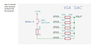
The D2A can be accomplished with resistors:
picod2a1.jpg
See https://datasheets.raspberrypi.com/rp2040/hardware-design-with-rp2040.pdf Section 3.2 VGA video.

The pico has enough io with pins to spare. The way they do the io is UNUSUALLY fast (in my opinion).


This means, it may be possible for ~$10 to have a CGA to VGA circuit that is, in fact legitimate VGA that is going to work with all those discarded / thrift shop monitors that have a VGA 9 pin connector.....at least that is what makes it compelling and addresses your point of why go to the trouble.....

Now, you need power and you need to go through 3.3v/5v and back - so a few bipolar or mosfets and a couple of resistors, or a cheap but fast translator board (they are maybe $1 now).

My thinking at the moment, rightly or wrongly, is that you do not have to go find that monitor
NTSC/PAL 31khz video frequency range.

I can't yet wrap my head around the intensity and synch lines, but in some examples I have been reading about, the pico is generating those, so using the existing signals should be easier...maybe.

Remember, I just went through buying a monitor at a thrift store for like $12 or whatever it was and it gives nothing but heartache with that circuit.


I really do appreciate the input. You know more than me and that is how I learn, but that is my thinking.

Yes, I will put the RCA on the list if I can - looking through it just now I do not see an easy way of doing it but will get back to that.

Thanks again
 
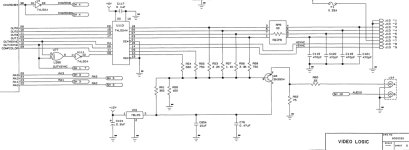
If you’re happy with monochrome output from your CGA card (which is all you’re going to get with that circuit) I would actually suggest a modification: as it’s written it only uses the “Green” and “Intensity“ lines. That’ll work okay with white (and green/yellow/cyan, sort of) text but any red/blue/purple text isn’t going to show up *at all*. Instead I’d suggest using four resistors on all of RGBI to give you a full 16 shades of grey.

For suggested values/ratios of these resistors look at the schematics for a CGA card upstream of the composite out. (Which I assume your card doesn’t have.) The Tandy 1000 service manuals have a nice clear layout for this, the resistors are hanging in parallel off the same lines going to the digital port. Mix in the sync as that schematic you’re working from shows.

(* The exact ratio of the resistors you use doesn’t really matter that much, I’d just suggest using the same weighting as a real CGA so anything running on it won’t look “off” compared to the same thing running on an IBM with a composite driven monitor, like a 5155.)
This was a good suggestion - thanks, and I recently added R and G to the circuit. Here is exactly what I did.

First off, I do have a composite signal on that board. It comes through on pin 7. After a *good* deal of testing, I am convinced that it is PAL and just below what my monitor can lock. I have, on a few occasions seen a fluttering screen. I gave up on it.

As you suggested, I looked around for a Tandy schematic and, indeed found one with the relevant portion easy to understand.
tamdy1000videoR.jpg

They have R-2.2k / G-1.1k / B 3.3k. Recall that the original circuit had 820 on G. First, I substitute a 2.2k for the 820 and it still worked - I just wanted some assurance.

I ended up using R-1.5k / G-820 / B-2.2k

With G only, you get this:
without grey scale 20230717_114134.jpg

Adding R and B, you get this:
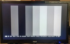
with grey scale 20230717_200855.jpg

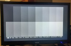
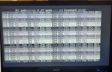
Here is the real test and I think it passes quite nicely for composite video (I should tune up the monitor a bit - oh, and take the circuit off of the breadboard.
All grey scale 20230717_200205.jpg

BTW: I went looking through old code to get some screens to test and found a really nice program from MobyGamer here. The download link is here. In my view it is done quite well and was exactly what I wanted.

Finally, I will likely checkout the CGA->VGA mod that was discussed a bit here (6 resistors and 3 diodes) and in greater length elsewhere. I will remain optimistic and do some bread board tests and so on before hook up. I am [always] a bit pessimistic - just because this monitor can go down to NTSC does not mean it will do VGA at that sync frequency - but maybe I will be able to post some color screens soon :) Happy if it can.
 
And yes, also this (simple) circuit needs a monitor which can support the NTSC/PAL 31khz video frequency range.

I tried this method and it did not work on the RCA RT1970. The composite BoginJr circuit did work and the addition of all three lines (RGB) gives a decent "grey scale", at least for me.

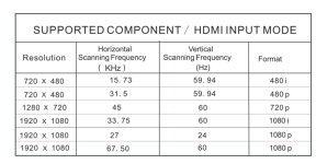
The circuit that you describe is so simple that yes, I gave it a try - especially since this monitor would work with the BoginJr circuits. BUT...that is only for the component/HDM inputs, e.g., 15.73KHz.

rca1.jpg


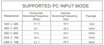
When it didn't work, I read "the rest" of the manual - the VGA input, still needs the 31.5 KHz (or higher) Horizontal.

RCAPC.jpg
Oh well,
 
Since I started this thread, I wanted to update everyone on exactly where the quest is at - and thanks are due to many of the folks on the board.

First off, as mentioned, I built the circuit by @deanimator and, incredibly, managed to move it from a breadboard to a soldered board. No, not pretty (they never are with me).
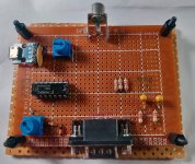
bogin cga2composite 20230917_134012.jpg

As suggested by @Eudimorphodon I added B and R and this is the modifications that I actually used from the original circuit, which was linked in the first post. I used what I had and you can see that on the "check off" schematic sheet that I used.
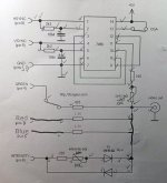
comp schem 20230917_141759.jpg
Again - this is not a circuit that I designed - see the first post. I simply modified it a a bit and substituted some components because I had them on hand. It works and, for me, it works very well! It got me actually using the machine and in the process, learning a whole lot about CGA and video, in general.

Of course, I did crave color and recently purchased an RGBtoHDMI - 6 bit edition
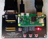
cga0 20230928_103208.jpg

This product is based on the open source project (thanks @IanB and others). I can't do it justice here so go here and here to learn about all the details. It works very well for me and is flexible beyond my current needs.... a couple of screen shots to illustrate...
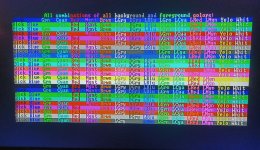
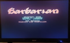
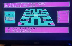
cga1 20230919_001314.jpg
cga2 20230919_000408.jpg
cga4 20230919_000938.jpg


One very nice feature is that it works with an HDMI to VGA cable - this one is what I used, and yes, it is active so there is an additional ps involved....BUT, it means that I can use the old thrift store monitor that I posted here.

Looks decent and I don't have to dedicate my RCA monitor to the XT!
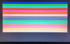
cga3 20230928_103313.jpg
 
Last edited:
Back
Top