• Please review our updated Terms and Rules here

M24SP DB25 to DB9 adapter

Stop urging me to remind myself that I haven't fixed the main problem with my color monitor that prevents it from functioning.... :mad1:
 
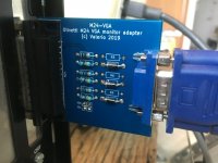
M24-VGA prototype

M24-VGA prototype

I have tested this simple solution suggested by 1ST1 and the short summary is that it works... more or less!

This turned out to be quite a long topic so I will split it into two posts:

1) description and photos of the output (this post)
2) problems and further considerations (next post)

This is what the PCB looks like:

CFE1FA1C-D7DB-4036-B522-5A65F391C490.jpeg

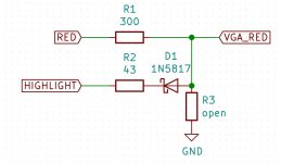
and this is the schematic I used is this (the same for all colors):

6281BE46-1DD5-411A-8609-11F6C0FE3158.jpeg

The values of R1 and R2 were chosen so that the observed voltages at the VGA output were around ~0.5V for "low" intensity and ~0.7V for "high" intensity. These depend on the forward voltage of the diode (around 0.37V for 1N5817) and (crucially) on the voltage level at the M24 video output. This is nominally TTL "high" or 5V, but in reality it depends on how much current we are drawing from those outputs and it can be as low as ~3V. More on this in the next post.

I did not actually put in an R3 resistor. This may or may not be a good thing. For steady-state voltages (DC), the VGA cable + monitor act as a 75 Ohm load. So you can think of R3 being inside the VGA monitor and being 75 Ohm, and being part of a voltage divider with R1. When Highlight is high, no current flows through the diode and that's it. When Highlight is low, some additional current flows through R1 and then R2 and the output voltage drops a bit. So far so good.

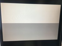
In order to test it I wrote a very simple program that creates two vertical bands of color next to each other on the screen, the left one with highlight off and the right one with highlight on. The connected VGA monitor is a NEC MultiSync LCD 1990FXp.

This is what it looks like for color blue:

BE8C58B2-D805-436B-AACF-C1E6C0A3F1B0.jpeg

(NOTE: the orientation of all the photos is wrong - the bands are vertical, not horizontal)

Now you can see two things:

1) it works! the left side is clearly darker than the right side (well, it's clearly visible in real life - hard to make it show in photos though)
2) there is a vertical white line at the center of the screen between the two bands of color (approx 1 or 2 pixels wide). More on this in the next post.

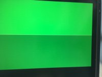
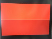
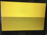
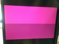
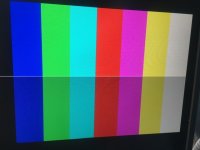
This happens for every color. Here are the other colors:

FCD1C4DC-6C61-4A20-BCE4-9176B3488F8F.jpeg
2A876C42-28C7-40F0-A557-0DD3090D6049.jpeg
BAC3230B-8047-4411-9E5B-29B7BD05F352.jpeg
5C85B04F-B336-422E-AE4D-687286BD9D07.jpeg
DD61598E-0F13-41CE-9866-E02B322D9210.jpeg
63CEF041-6BAF-4C97-886D-B9F2BD32FD4B.jpeg

The red one looks a bit weird in the photo but in real life they are fine, with dark red and light red. Yellow looks as expected, ie light yellow and dark yellow, not brown.

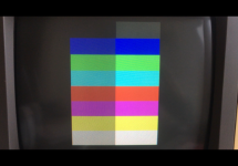
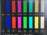
Here are all the colors next to their highlights in the same screen:

FFCCD8EE-521F-4586-9091-89426E7391AE.jpeg

I also got my hands on an original AT&T 6300 color monitor. Here is a photo of the same screen as above:

IMG_0053_small4.PNG

Note that dark yellow looks yellow, not brown! I was surprised to see this, but this means that the original monitor essentially shows the same yellow as this adapter.

One difference is the "light black" or "dark grey" color. This is when R,G,B are all zero but Highlight is one. In this adapter this still shows as black, but in the original monitor this is actually visible as dark grey. This adapter cannot reproduce this.

Finally, this is the screenshot from the CUSTOMER.EXE program:

E1160658-2907-41AD-809E-0BAABED3596C.jpeg

It's harder to see from this photo but the light colors are indeed lighter than the dark colors.
 
Last edited:
M24-VGA: problems

M24-VGA: problems

Now for the problems.

Current draw

One thing that bothers me is current draw. The output stage of the M24 RGBI signal is an SN74S374N. As per the datasheet (page 9), the maximum output current in the High state is 6.5 mA. This is very low.

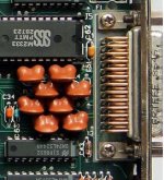
Even if nothing is connected externally to the DB25 connector, each of the outputs of the SN74S374N is loaded with a 390R resistor and a 120pF capacitor in parallel on the video board itself:

output_stage.JPG

I have no idea why, if anyone knows pls shout! These are the orange components seen on the video board near the DB25 connector. Each capacitor/resistor pair seems to be bonded in one package - again, no idea why:

output_passives.JPG

Anyway, even without external loads, this means that each output draws a nominal 5V / 390R = 12.8mA !! Any external loads would be in parallel to this, drawing even more current. Indeed the '374 gets quite hot if you connect anything less than ~400R as an external load. I can't imagine how hot it gets if you just use the simple straight-connection VGA adapter with no resistors (where the load would be just the 75R VGA termination) - I know it still works, but surely it can't be good for the longevity of the IC.

This may or may not be related to the next problem:

White lines

As I mentioned in the previous post there is a vertical "white line" between low and high intensity color bands.

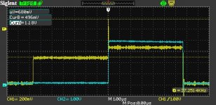
In order to investigate a bit further I hooked up an oscilloscope to the adapter:

Spike_with_HighlightCH2.jpg

The blue trace is the Highlight pin on the M24. As expected halfway through each scan line it goes from "low" (~0V) to "high" (~4V).

The yellow trace is the VGA output of the adapter for a given color (red in this case, but they are all the same). Note that the vertical scale is different from the other trace. We see two main voltage levels, corresponding to the two vertical color bands. The left part corresponds to the "dark" color band (output voltage ~0.5V) and the right part corresponds to the "light" color band (output voltage just under 0.7V). However between the two bands there is a clear voltage spike.

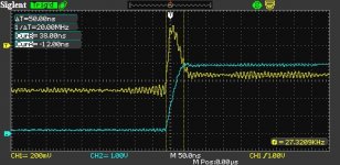
Here is a close-up:

Spike_timingdetail_with_HighlightCH2.jpg

I don't know if this is caused by the '374 being overloaded an not being able to respond quickly enough (50ns rise time is way above spec for this IC) or by the VGA cable transmission line not being properly terminated at source. Any ideas, pls do let me know.

When I get the change I plan to test a few more setups (maybe without the cable, just with a 75R load resistor after the adapter). An alternative design could be to just use FETs to drive the VGA colors from the +15V on the connector. I know Chuck suggested this earlier on - I should have listened :) - but I think this needs a BJT to drive each FET (unless someone can come up with a single-transistor design!).
 
Last edited:
This is a great write-up, I've always wondered if this was possible!

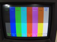
I'm not sure #6 is supposed to be yellow on those monitors. (Not that you can correct for it in your circuit, but it's important to note the difference.) I'll set up my 6300 and take a picture to verify.
 
I would buffer those analog RGB signals through a THS series amp from TI. DC coupled on both ends. You would need to get +5 somehow to power it. If it's not available on the digital RGB output connector throw a 7805 on there and grab the +15
 
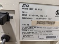
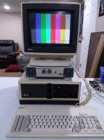
Not to worry you, but on my CRT319 it is indeed brown:

IMG_20200427_183051.jpgIMG_20200427_183129.jpgIMG_20200427_183205.jpg

Not that you can do anything about it, but I wanted to let the record show that the CRT319 shows brown, which is also what I remember growing up with. I can try to test with a Xerox 6060 monitor and I think I have a CRT318h if it's really needed, but if possible, #6 is supposed to be brown.
 
I would buffer those analog RGB signals through a THS series amp from TI. DC coupled on both ends. You would need to get +5 somehow to power it. If it's not available on the digital RGB output connector throw a 7805 on there and grab the +15

I was thinking about using an amplifier - I even have an LT1254 which I could use, and which (I think!) would work with a single +15V rail (no 5V rail is available on the DB25 connector). An amplifier IC is probably the best solution but I was resisting it as somehow it seems like a bit of a waste - it’s just two levels after all, it should be doable with discrete transistors :)
 
just watch your slew rate, most important thing with video amps IMO is not limiting your bandwidth
 
Not to worry you, but on my CRT319 it is indeed brown:

View attachment 60514View attachment 60515View attachment 60516

Not that you can do anything about it, but I wanted to let the record show that the CRT319 shows brown, which is also what I remember growing up with. I can try to test with a Xerox 6060 monitor and I think I have a CRT318h if it's really needed, but if possible, #6 is supposed to be brown.

Thanks for double checking! And good to see that your 6300 is up and running!

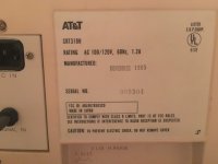
This might be the difference though - my monitor is a CRT318H, not a CRT319!

BB609BF0-68D2-4D5F-98A4-3934A248E4BE.jpeg

Also it’s interesting to note that the CUSTOMER.EXE color page says “yellow” and “light yellow” rather than “brown” and “light yellow”. If I can find the original Italian version I could check what it says there...
 
It's my last working 6300 -- I have three others that won't POST :-(

It may interest you to know that when I run CUSTOMER.EXE on this setup, it says YELLOW and LIGHT YELLOW even though the monitor clearly shows brown. Sadly, I don't have the timeline or justification as to when the 318h and 319 came out and why they are different. But any video at all is better than none, so please keep working on your circuit :)
 
Hello, this just looks great! Thanks for the effort. I will take definitevly some of the final version adapters.

You may have again a look into the german forum, the guy there uses a TTL gate to amplify the signal output of the video card (there it is a Hercules card). Maybe you can use a single 74LS244 (bipolar TTL) or better 74HCT244 (unipolar CMOS).

See here: https://forum.classic-computing.de/...tplan-mit-bastel-an/&postID=223793#post223793

As soon it works fine, someone may also test it with other CGA and EGA cards...? (but there you need power supply for the adapter)

By the way, that integrated resistor/capacitor thing (which looks like breasts) is signal filtering for better EMC compatibility..
 
Hello, this just looks great! Thanks for the effort. I will take definitevly some of the final version adapters.

You may have again a look into the german forum, the guy there uses a TTL gate to amplify the signal output of the video card (there it is a Hercules card). Maybe you can use a single 74LS244 (bipolar TTL) or better 74HCT244 (unipolar CMOS).

Thank you. I thought about a 244, but (at least on paper) they do not look fast enough for the M24’s dot clock of 24MHz...
 
Dear All,

I would like to add my contribution to the discussion on this thread about analog/digital, dark yellow/brown etc.


1) The M24 has digital video out. R G B + I. This has already been clarified in the thread.

2) The BROWN color on the CRT318H, CRT319H (H should stand for HITACHI … it would be nice if someone who has these monitors could check if the monitor manufacturer is really Hitachi and what is the Hitachi Model and Chassis Name), is created by a special circuit in the color digital/analog processing in the monitor itself, like it has been designed by IBM for the first time in their 5153 monitor.

The CGA card (for both IBM XT and Olivetti M24/AT&T PC6300) can only create dark yellow.

The monitor has a special circuit who is able to cut the green voltage when the digital combination of R G B + I instructs the monitor to display a dark Yellow (Color Code number 6). The IBM created this to have brown instead than dark yellow (color number 6) and dark grey instead of black, for color number 8.

I believe Hitach has replicated this behaviour of IBM 5153 color monitor. The special circuit can be found in the schematics of the IBM monitor, in the reference manual.

At the website:

https://www.aceinnova.com/en/electronics/cga-and-the-brown-color-in-ibm-5153-color-display/

you can find the explanation and a link to download the IBM Technical Reference Manual. IN the site there is the picture taken from the manual. The darkened side of the schematics is the special circuit to implement this behaviour.

The Toshiba or Mitsubishi color monitor for the M24 or the AT&T CRT318T, are TOSHIBA and can handle only dark yellow, not brown, as they don't have such special circuit.

Olivetti in Italy also sold Mitsubishi color monitors, but I don't know if this monitor was also sold as CRT318 to AT&T (because there would have been a CRT318M, probably, but I never heard this model).

IBM was the only company implementing this, at the time their monitor was sold. All the other were displaying dark yellow. Probably Hitachi has implemented the same feature later. Don't know if IBM patented this modification.

That is why the AT&T version of the Customer Test displays dark yellow (or maybe it recognizes the type of monitor, if either CRT318T, or CRT318H/CRT319H) by displaying the appropriate text.

While Olivetti's has only Dark Yellow.

I didn't read all the very long thread, so in case anybody has still questions, thanks to let me know.

Hope this clears the topic.

On the other side, I'm building a couple of board MCE2VGA 2.0 designed by Luis Antoniosi.

https://sites.google.com/site/tandycocoloco/mda-cga-ega-to-vga
https://github.com/lfantoniosi/mce2vga

I had the idea to modify the VHDL Source Code to include the management of the Olivetti M24 24Mhz Video output.

The problem is: according to Luis Antoniosi's investigations, the speed of the static RAM for the frame buffer, should be maximum 5ns of access time, not 8 as in his project.

Unfortunately there is no such static memory that has the same footprint (44 TSOP-II) of the one used in Luis Antoniosi's project .

Modify the VHDL to include the management of 24Mhz shouldn't be a problem (even though I'm not a master in VHDL).

Problem is the access time of the static memory chip and its package.

By re-engineering the board and using a different package of the static RAM (it seems there are on the market static RAMS with access time of 5ns with a different package), it would be possible to implement it.

But I'm not skilled in PCB design.

Maybe someone here could think about it. So we have a real conversion with a frame buffer.

Is anybody actually using the MCE2VGA for the IBM PC or other computers? I've read the board has some problems of lagging etc. Thanks to share your experiences.

Of course the board should also be changed to support a DB25 connector, or we could use a DB9 to DB25 converter when the AT&T/Olivetti video output is used.

Bye
Vincenzo.
 
Hello Chuck(G).

Do you believe me if I tell you that in Italy the serial connector with 9 pins is called DB9 and the parallel port (Centronics) connector with 25 pins is called DB25? :)

So, actually, if I tell it in the Italian way I should write as I did. A DB25 to DB9 adaptor to plug the output of the M24 indigenous board to the MCE2VGA from Luis Antoniosi.

In the US it should be DE25 to DE9 adaptor, then.

But I am happy anyway we both understand, despite the different language conventions, the meaning of what I wrote. :)


Vincenzo--a small "nit" It's a DE-9 ("E" sized connector with 9 pins) A DB-9 would be a very different animal.
 
Hello Chuck(G).

Do you believe me if I tell you that in Italy the serial connector with 9 pins is called DB9 and the parallel port (Centronics) connector with 25 pins is called DB25? :)

So, actually, if I tell it in the Italian way I should write as I did. A DB25 to DB9 adaptor to plug the output of the M24 indigenous board to the MCE2VGA from Luis Antoniosi.

In the US it should be DE25 to DE9 adaptor, then.

But I am happy anyway we both understand, despite the different language conventions, the meaning of what I wrote. :)

no bro the country is irrelevant

people misusing the D-subminiature shell size codes is a global panedmic

DB-25 is 25 pin serial / parallel

DE-9 is 9 pin serial

DA-15 is joystick
 
Back
Top