• Please review our updated Terms and Rules here

Memory board for the IBM 5170

ab0tj

Experienced Member
Joined
Mar 4, 2015
Messages
116
Location
Colorado, USA
Hi all,

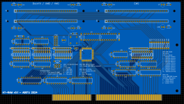
Just wanted to share what I've been working on lately. This is a 16 bit ISA expansion card that provides 8MB of system RAM and 8MB of EMS RAM. It uses 30-pin SIMMs, because I have always used SRAM for projects and wanted to play around with DRAM for once. Boards have been ordered and I'll update the thread as the project progresses.

Screenshot from 2024-04-03 22-08-44.png
 

Attachments

  • Schematic_AT-RAM_2024-04-03.pdf
    454.5 KB · Views: 4
Last edited:
The backfill switch settings do seem confusing. Backfill replaces memory on the motherboard typically so a 512K or 640K mainboard would only be able to use 256K with the other 384K from the expansion board making up a large EMS page frame to quickly swap applications under DesqView. I am not sure that the motherboard memory could be reduced to zero because it is necessary to have enough memory to load the EMS driver to permit the backfill operation.
 
That's the term used by most expansion memory boards, at least that I'm familiar with. See the manual for the AST RamPage Plus 286, for example.
In that manual, 'backfill' is used as a verb, e.g. "RampagePlus 286 will backfill conventional memory to 640 KB from the amount set on the system board."

So, conventional memory being used to top up what conventional memory exists on the motherboard.
 
The backfill switch settings do seem confusing. Backfill replaces memory on the motherboard typically so a 512K or 640K mainboard would only be able to use 256K with the other 384K from the expansion board making up a large EMS page frame to quickly swap applications under DesqView. I am not sure that the motherboard memory could be reduced to zero because it is necessary to have enough memory to load the EMS driver to permit the backfill operation.

The backfill switches add system memory independently of the EMS page frame. It's not likely the "0-128k" setting will ever be used, but turning on switches 3, 4, and 5 would bring a 256k system up to 640k for example. EMS is a separate thing and shows up in a 64k block of memory that will be set by the EMS driver at boot.
 
In that manual, 'backfill' is used as a verb, e.g. "RampagePlus 286 will backfill conventional memory to 640 KB from the amount set on the system board."

So, conventional memory being used to top up what conventional memory exists on the motherboard.

I guess in my mind it is a verb here, "backfill enable" meaning to enable the board to backfill memory in those areas. But I'll keep that in mind for v0.2 of the board...
 
Just to clarify, the EMS support you're planning for here is the standard "EMS 3.2 hardware" scheme with four 16K pages in a 64K page frame? (IE, there's no EEMS/EMS 4.0 large pages/dynamic mapping outside the page frame?)
 
Just to clarify, the EMS support you're planning for here is the standard "EMS 3.2 hardware" scheme with four 16K pages in a 64K page frame? (IE, there's no EEMS/EMS 4.0 large pages/dynamic mapping outside the page frame?)

Correct. The CPLD I'm using at the heart of it can barely handle that as it is... I may look into EMS4.0 support in a later version of the board.
 
I don't even recall the 16-bit memory expansion boards being terribly popular back in the day. I had a couple of them, but probably only because I got them at good prices. The combination of 80386 boards plus the availability of 80286 boards that could support 4+ MB of DRAM pretty much limited the market back then. The ones I picked up were at fire-sale prices.
 
Correct. The CPLD I'm using at the heart of it can barely handle that as it is... I may look into EMS4.0 support in a later version of the board.

I've been kicking around a design using a SRAM chip as a pager; there are pretty cheap 64kx16 bit SRAMs with sub-20ns access times. That gives you 16 address lines to play with; EMS 4.0 allowed up to 64 alternate register sets, that's six bits, and you only need another six bits to chop the bottom 1MB of address space into 16K pages. (The four left over are actually enough to do 16K pages across the whole 24 bit ISA address range, although that's outside the EMS standard's interests.) In the other dimension the 16 bit wide memory would let you accommodate 256MB of RAM (8 times more than the EMS 4.0 standard officially supports), so... yeah, I think that would solve the register capacity issue, and the speed should be enough.

The trick, of course, is writing a suitable driver to use it. That's way, way outside my personal wheelhouse.

Agreed, that would be a great way to go about it. The problem I ran into when exploring SRAM-based options is the control logic that goes into making it work... You have to deal with the fact that reading vs. writing the SRAM involves an entirely different set of data and address signals, along with the fact that you likely can't map the whole SRAM into I/O address space. These are all problems that can be overcome, but I wanted to keep this board fairly simple and verify that I can even make it work before getting deeper into it. The 74LS612 chip used in the 5170's design also looks like an interesting option, though it is a bit slow and wouldn't be nearly as flexible as your way of doing it.
 
You have to deal with the fact that reading vs. writing the SRAM involves an entirely different set of data and address signals, along with the fact that you likely can't map the whole SRAM into I/O address space.

Yeah, it's definitely a hassle that you have to multiplex both the address and the data lines of the mapping RAM depending on if it's doing its normal role of address translation vs. being written. (Or read; the latter could technically be optional, but being able to read its state could save you from having to maintain a potentially very large state table in the driver. Maybe a clever fix there would be to actually have the driver use a page or two of the EMS RAM to mirror the state table?) My sketch of the design basically solves the I/O space problem with latches, IE, instead of trying to directly match 64 page locations covering all of the 1MB conventional memory state you'd write the address of the page you want to update to a latch in one operation and write the page value you want to deposit in it in a second operation.

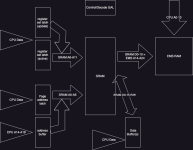
If we imagine a maxxed-to-the-EMS-4.0 limits version of this, IE, being able to map a 16K page to *anywhere* in the bottom 1M address space, having 64 alternate register sets, and access to 32MB of expanded RAM this is about what I picture about the minimum of moving parts; this comes to seven or 8 discrete packages assuming standard TTL packages for the buffer/latches and a GAL for the control logic. I would *guess* you could fit it in a mid-size CPLD?:
EMSMAPPER.drawio.png

This is a 20 minute diagram I just slapped up because I'm not near my kicad model. To clarify a bit, the "page address latch" is used to hold the address for the 64 possible "page frame" slots in the conventional RAM 1MB space that you might need to update, and its output is multiplexed with the CPU's A14-A19 address lines by switching which output is enabled on their shared connection to the SRAM when an IN or OUT is performed at the separate update register port address. On the other side of the chip you have the SRAM's data lines normally driving the top 11 address lines of a total 25 bit addressable memory space in the EMS RAM block; during an update for a register both the SRAM's data lines and the EMS RAM's address lines will be driven by the CPU data write buffer... which should be fine because, well, the CPU is in the middle of a port write operation, it shouldn't matter if the EMS address lines are in flux during the operation. I think reads should be fine too. This schematic *is* assuming we can do 16 bit-at-a-time data transfer, if we did 8 bits at a time things get a little more complicated, but not too much.

Note that the reason I showed *two* register set latches is because there might be a need to modify registers in a different set than the one you're actually running out of? I haven't dug into the full details of the EMS 4.0 standard to know if that would be an absolute necessity, it might be something you could paper over in the driver, but it seems reasonable.

We're only actually using 4K's worth of 16 bit words with this thing, which might seem like a little bit of a waste when the RAM chips I mentioned could hold 64Kx16 but, well, they're cheap. We're also only using 11 bits on the output side; I don't know if there would be any useful tricks you could do with the other five bits, like implement, I dunno, read/write protection flags or something? But the capability to play with such ideas is there.
 
Last edited:
… was thinking about it, and an all-too-clever way you could use some of the extra bits on the output side would be to implement the memory map *decode* in software. IE, the driver for this board, which would load before anything else, would program a bit position in all 64 conventional memory register slots with a “1” or “0” denoting whether that page was to be decoded, and then flip a bit in the control logic telling the address decode to take that output into account. Then you wouldn’t need jumpers/switches to define anything about the EMS page frame position, conventional memory or UMB backfill map, etc. At power-on the only thing enabled would be the I/O port.

Of course if you were doing conventional backfill your driver would have to be smart enough to adjust the BDA top of memory appropriately and, more tricky, deal with the possibility that a bios extension is using the top of memory for something and move it. The drivers for the most sophisticated EMS memory cards that supported large pages had to deal with this stuff too, which is why I think the by-far hard part of this isn’t the hardware, it’s the drivers.
 
Back
Top