• Please review our updated Terms and Rules here

Mitsubishi M4851 360K Drive Reads - Won't Write

notneb82

New Member
Joined
Dec 7, 2021
Messages
8
Hey folks,

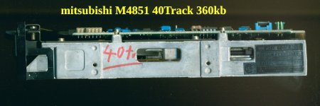
I have a Mitsubishi M4851 360K drive that reads disks without any issues, but it refuses to write to any. All of the disks I have tested do have the notch in them to allow the drive to write and are 360k formatted. I managed to find a manual online for the drive and browsed through it to see if perhaps there is a jumper or dip switch setting that could give write protection even if a disk has the write-notch. The only thing remotely close in the manual is a setting called 'write-protect inversion'. Now, I may be thinking of this setting incorrectly, but could this mean that if the notch is not present or covered by a piece of tape the drive can write to the disk and if the notch is present it is write-protected? I went ahead and tried a disk with a piece of tape over the notch but the computer still says all disks are write-protected.
At this point, I'm wondering if it could be the write-protect sensor malfunctioning. How would I go about testing the write-protect sensor? Seems it is an IR LED and if the beam is interrupted, write protects the disk. Is there a good way to test the diode and sensor for proper function? Does anyone know if this is a common problem with these drives?
 
This is my drive, working well under MSDOS.
 

Attachments

  • Mitsubishi_M4851.pdf
    1.6 MB · Views: 6
  • m4851-112m_1985_1.jpg
    m4851-112m_1985_1.jpg
    376.5 KB · Views: 7
  • m4851-112m_1985_4.jpg
    m4851-112m_1985_4.jpg
    682.1 KB · Views: 7
Should be able to check it on pin 28 of the interface. I had one go out on an 8" tandon drive. I used a scope on a test pin, but a volt meter on pin 28 should work. I could easily see the change when inserting a non write protected floppy, didn't even need to close the latch.
 
We used that feature to indicate whether a disk had been changed by polling the write-protect status about every 250 msec. Never failed on the drives we used.
 
Should be able to check it on pin 28 of the interface. I had one go out on an 8" tandon drive. I used a scope on a test pin, but a volt meter on pin 28 should work. I could easily see the change when inserting a non write protected floppy, didn't even need to close the latch.
Working out whether the problem cause is in the drive, or elsewhere (cable or controller). The example of a Tandon TM100-2 is shown at [here]. The drive needs to be selected, and according to the M4851 OEM manual, that can be (easily) done temporarily using the MX jumper.

1715809443699.png
 
Thanks for the replies, everyone. I just wanted to follow-up that I did some hardware swapping to eliminate the computer, floppy controller, and floppy cable. I pulled the drive from the Leading Edge MP-1673L that the drive came in and inserted it into a Gateway PII system that supports 360K drives. I keep a 1.2MB drive in that system so it has a floppy cable with card edge connections on it. The drive exhibited the exact same behavior as it did while installed in the Leading Edge. I then took a 360K drive out of an Epson Apex to test the Leading Edge's cable and floppy controller and it worked as expected, both reading and writing - so I do believe the issue is isolated to the Mitsubishi drive.
 
... so I do believe the issue is isolated to the Mitsubishi drive.
Is there a good way to test the diode and sensor for proper function?
It is a pity that the OEM manual that @fritzeflink pointed to, does not contain a circuit diagram.

Does your drive match the photos of fritzeflink's drive, or is very close ?

I ask because of what I see in the bottom left of the third photo; the write-protect related component denoted as "WP". That is either the sensor or the LED, and considering the board markings of 'SG' and 'S', I figure that it is the sensor. The 'G' in 'SG' possibly means that that pin is grounded, supported by the thick trace, which can be seen to be heading off to the HM jumper and the screw. If so (sensor + SG is grounded), then using a multimeter, expect to see the voltage on the 'S' pin change when you insert a floppy. Maybe fritzeflink will confirm that behaviour on his/her drive.

1715823371892.png
 
It is a pity that the OEM manual that @fritzeflink pointed to, does not contain a circuit diagram.

Does your drive match the photos of fritzeflink's drive, or is very close ?

I ask because of what I see in the bottom left of the third photo; the write-protect related component denoted as "WP". That is either the sensor or the LED, and considering the board markings of 'SG' and 'S', I figure that it is the sensor. The 'G' in 'SG' possibly means that that pin is grounded, supported by the thick trace, which can be seen to be heading off to the HM jumper and the screw. If so (sensor + SG is grounded), then using a multimeter, expect to see the voltage on the 'S' pin change when you insert a floppy. Maybe fritzeflink will confirm that behaviour on his/her drive.
It is a pity, would make things easier but my drive seems like it's an earlier revision since it does not have as much integration as fritzeflink's. Here are pictures of my M4851.
 

Attachments

  • thumbnail_IMG_2595.jpg
    thumbnail_IMG_2595.jpg
    871.4 KB · Views: 11
  • thumbnail_IMG_2597.jpg
    thumbnail_IMG_2597.jpg
    257.1 KB · Views: 10
  • thumbnail_IMG_2596.jpg
    thumbnail_IMG_2596.jpg
    254.3 KB · Views: 10
Don't forget, a dust bunny in the wrong spot will also cause this issue.

At a guess, in the lower left of the first pic, the red&black are the IR led and the yellow&white are the sensor. All the ones that I'm familliar with use phototransistors as the sensor. I think both the led and the phototransistor test like diodes.
 
It is a pity, would make things easier but my drive seems like it's an earlier revision since it does not have as much integration as fritzeflink's.
In a way, that is good, because if the faulty component is a chip, then a 7400 series TTL chip is easier to source compared to the LSI chips on fritzeflink's unit.

I think both the led and the phototransistor test like diodes.
The phototransistor is a transistor with the base not exposed as a pin/lead. Therefore, from a measurement perspective, are two back-to-back diodes. A multimeter will not be able to test that.

The DC voltage on one of the four leads (specifically, one of the two sensor/phototransistor leads) is expected to change very significantly (in the order of volts) as soon as a floppy in inserted to the point that the floppy blocks light from the LED. The diagnostic direction taken then depends on whether or not that is observed. Examples:
- If observed, work out which chip the sensor/phototransistor is connected to.
- If not observed, verify that the LED is being supplied with power.
 
I scoped both the LED and phototransistor. Both never changed value whether or not a disk was blocking the sensor.

Measuring the diode: Red wire: 1.26V, Black wire: ground

Measuring the phototransistor: Yellow wire: 5V, White wire: ground

The diode's input voltage seems awfully low to run it - I've never seen an old diode that runs at such low voltage. I measured at R25 which, according to the diagram, should be a 150ohm resistor, input voltage is 5V and output is 1.26V - that seems like a steep drop for just 150ohm.
 

Attachments

  • IMG_2607.jpg
    IMG_2607.jpg
    3.9 MB · Views: 3
Got a digicam? Take a peep at the LED with it and see if it's glowing (Digicams do better at seeing near IR than you do.) Normally, you'd expect a drop of about 2V across an LED.
 
Here are two samples of 10 Degree Top Viewing IR LED's that are 100ma MAX Current and 1.5 VDC Forward Voltage,
with a MAX of 1.7 VDC. They are about 5.7mm OD. Amazon has some that are 3mm OD and a matched
Source & Receiver. (No information about their Beam width or direction.)


I've got some New Old Stock H21B3 Optics (Slot Oriented) if yours is similar to the H21B3 Optic.

Larry
 

Attachments

  • SFH 4555_EN.pdf
    1.1 MB · Views: 0
  • SFH 4545_EN.pdf
    1.1 MB · Views: 0
Hi folks,
First, I wanted to thank each of you for your help, suggestions, and resources. The schematics and manuals were very valuable.

Next, I wanted to share my final findings and resulting fix.
The underlying issue was a completely faulty photointerrupter. It ended up that both the IR LED was dead and the phototransistor was faulty as well. I was rummaging through my toolbox and came across an old Radio Shack IR sensor that I recall buying back in the 90's, so offering it up next to the IR diode showed that nothing was being emitted, of course I tested the Radio Shack sensor with a TV remote to make sure it's still good. Next, the phototransistor's yellow wire had disconnected deep within the sensor's package and went unnoticed for a while with no real hope of reconnecting it without tearing up the sensor package.

IMG_2610.jpg

To fix the drive, I ended up bypassing the sensor by inserting a 100ohm resistor where the yellow and white phototransistor wires were (you can see in the attached picture a test bodge, once it tested as working I cleaned out the through holes and trimmed the resistor's leads down). This is allowing the drive to write finally. I do understand that this makes it so that any write-protected disks are at risk, but it's fine for me, the drive is fully usable now and I don't use original disks, just images written to blank disks so accidentally overwriting a program is of no real concern, would just have to re-image the disk.
Now I just gotta give this dusty thing a final cleaning.
 

Attachments

  • IMG_2611.jpg
    IMG_2611.jpg
    3.5 MB · Views: 4
Back
Top