• Please review our updated Terms and Rules here

Model 16 Renovation

In a perfect world I'd have all sorts of time to mess with the M16... Alas...

So, back to it. I have the foam to fix the keyboard but haven't gotten to that yet, but did want to run some diags...

IMG_1973.jpg IMG_1974.jpg IMG_1977.jpg

IMG_1978.jpg IMG_1979.jpg

IMG_1980.jpg

Now that I can run diagnostics, I'll drop in the 68K boards and see how they work...
 
It's a close approximation of the Model II/16 keyboard by a PS/2 keyboard. I've mapped all the keys so that they provide the correct bits, e.g., F1/F2, arrows, CTRL/KEY combinations, BREAK... I think the code would work with a USB keyboard as is with an appropriate adapter. Once I get the system booting into an operating system with an editor then I can check more out than I have.. Adjust the PS/2 typematic rate if needed and make sure my mappings all work as expected. Using some debug code they all seem to do what they should. Fun side project... Maybe make the keyboard lights chase, or something...

The difficult part was remembering how things like keyboard interfacing was done in the early 80s--very different world back then.. The Keytronics output looks a lot like SPI but with data active low and an additional 9th bit, but SPI it ain't. We didn't do a very good job on documenting the VDG card with all the board revisions and I admit to scratching my head a bit as Val and I worked through the logic. Anyway, I bitbang the whole thing.
 
Been awhile... Back to it!

Let's change out some keyboard pads.

IMG_2047.jpg IMG_2048.jpg

In the second photo above, the yellowish disk is the plastic disk that's clipped into the bottom of the well. That's all that remains of the original pad once I scrubbed out the old foam.

Removing the plastic disks:

IMG_2049.jpg IMG_2055.jpg IMG_2056.jpg


Pointing out the clips that the disk slips under--there are 4, but you can get by with just inserting the disk under 3:

IMG_2051.jpg IMG_2052.jpg

Plastic disk on the bottom of the replacement foam pad. This disk on a new pad will be attached underneath the clips:

IMG_2053.jpg

When placing the new foam pad into the keyboard well, I insert it from left to right trying to hook the plastic underneath the right-side clip. In the photo I'm clicking it under the left clip. Then I do the top clip and bottom last. By using the dental tool to gently pull up on each side I make sure that the new pad is secured:

IMG_2054.jpg

I ordered these pads from TexElec (texelec.com). Their product description is:

"105 "Foam and Foil" Capacitive Pads for KeyTronic Keyboard Repair"

No connection with them other than as a happy customer. I like their pads because they have new conductive Mylar discs so I didn't have to save the old ones which were in really bad shape... If you decide to use these pads for your replacement project, you can bypass the clean the well out with solvent step and just use a dental tool to flick out the whole thing. I didn't know this when I began, but went back and found the instructional video on the TexElec site that details the procedure.

Done with that! Sitting behind the M16 keyboard is the PS/2 keyboard adapter, still on the breadboard.

IMG_2057.jpg IMG_2058.jpg IMG_2059.jpg
 

Attachments

  • IMG_2049.jpg
    IMG_2049.jpg
    46.6 KB · Views: 1
  • IMG_2051.jpg
    IMG_2051.jpg
    51.8 KB · Views: 1
Power supply caps changed and Motorola video flyback transformer repaired...

View attachment 52563 View attachment 52564

Superglued the ferrite back together:

View attachment 52565
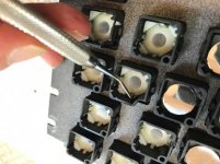
Now to replace it:

View attachment 52566

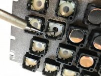
If you look at the tip of the screwdriver in this photo, there's a nut underneath that the brass rod screws into. Once the solder repair is done I tightened the nut to hold the ferrite securely, but not too securely..

View attachment 52567 View attachment 52568

I didn't get too wrapped up in making it fit like when it was new, only that it was all in place and secure. Also, didn't want to use too much heat around the ferrite.

Awsome work, I just scored a free Model 16 as well, Can't wait to start using it.
 
Anyone have a REPEAT key off of a Model II type keyboard they'd be willing to part with?

m16-missing-key-IMG_2062.jpg

Also wondering if someone would like to trade a 6000 style card extender for a Model II/16 type?

Thanks!
 
Fixing the Motorola card...

I'd been working with the machine when the video failed. Loud whine concurrent with a quick flash at the center of the crt face. My money was on a horizontal output transistor failure.

Getting down to it:

Pretty tight quarters around the Motorola video card for grabbing readings. If you're not just looking at connector signals or that which you can easily probe from the top, then you have to be creative. This is a technique I used at RS and it still works. Most everyone already knows this one, I bet, but it's here in case you don't.

IMG_2089.jpg IMG_2091.jpg IMG_2092.jpg IMG_2093.jpg

With the video CRT card removed, decide upon the signals you want to check and solder different colored wires, about a foot long, to each point. Goes without saying to make sure the solder job is good with no shorts. Reinstall the video board along with the power supply while carefully routing your "test leads" out and making sure the ends don't short to each other or to anything else. Fire up the scope, DMM, whatever you're using.

An isolation transformer for the scope (or any line powered test equipment) is a good thing in this instance! Couldn't find my isolation transformer, so I used a variac. Mine offers isolation, but I'm not sure that all do.

For testing, I was looking to isolate a large section where I might find a failure. You can see where I put my "test leads" on the schematic fragments along with a notation of the color of the wire I attached. I'd expected that this first pass would get me in the ball park and then I'd move these test leads to other points to zero in on the failure. Here's what I got:

IMG_2083.jpg IMG_2084.jpg IMG_2085.jpg

These signals are right on the money! Why no video?

I looked at the screen and this is what I saw:

IMG_2086.JPG

That's interesting...

While I was attaching leads I did fix some really crummy looking solder joints and since the CRT bleeder resistor was open, I replaced it with one of a close value (250 megohm 2 watt instead of 240 megohm). I doubt the bleeder would have solved this unless the the other wire under the "cap" from the flyback was not making good connection... I had to remove both leads from the cap to do the replacement.

OK! Well, that was easier than I expected.

Next shows the replaced bleeder resistor. There IS new HV heatshrink under the electrical tape, btw...

IMG_2090.jpg

There is still an intermittent that causes the screen to glitch some (quick, slight, shaking or changes in size). So, I'm not done, but I'm closer.
 
Last edited:
That looks very useful. Could it also be used with a 12/16B/6000 if a proper cable was made?

I think so since with a wiring adapter the keyboards are interchangeable. Timing is the same between the two keyboards.

The additional F keys need to be accounted for in my software, but that's the only change, I believe. I'll add that in.
 
Great thread. I restored a 16A last summer and had a great time with it. Have a Model II with a bad 68000 card I need to figure out now, your thread has me planning to start back this weekend.
 
Great thread. I restored a 16A last summer and had a great time with it. Have a Model II with a bad 68000 card I need to figure out now, your thread has me planning to start back this weekend.

Thanks! I've been having a good time with it, too... I should have been done with it by now, but I keep taking these tangential excursions and using the M16 as more of a test bed than a restoration at this point. One of these days I'll get back on track and finish it all up, but I'm having too much fun with it at the moment!

m16-vdg-tests-IMG_2116.jpg
 
Back
Top