• Please review our updated Terms and Rules here

Monitor doesn't always sync after ctrl-alt-del

SteveH

Experienced Member
Joined
Apr 30, 2003
Messages
301
Location
Shropshire, ENGLAND
I've got a Panasonic monitor that doesn't always sync correctly after hitting CTRL-ALT-DEL. I sometimes need to switch the monitor off and on several times before it displays the image correctly.

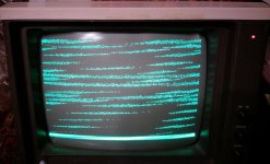
Here's what it looks like before CTRL-ALT-DEL:
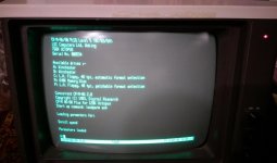
IMAG3374.jpg

And here's after:
IMAG3373.jpg

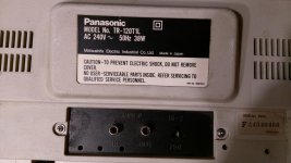
It's a 1980s Panasonic monitor, model TR-120T1L, and is attached to an LSI Octopus computer. I'm struggling to find any info for this monitor, so thought I'd ask here if anyone has any ideas on what may need adjusting. I've not re-capped this yet.
 
Hi,

The H scan oscillator is not going back into lock after the CRTL-ALT-DEL.

It is possible with this fault, that the problem (adjustment issue) is solely in the monitor. Aside from hitting CTRL-ALT -DEL (which will transiently kill the video out including the sync) simply try unplugging the video feed, and plugging it back in again. This may also show the same problem. If that happens the cause is simply an incorrect setting on the monitor's internal H hold preset (which might be accessible via a cabinet hole). There can be a marginal condition where the setting here is such that when the monitor is first switched on, there is just enough capture range on the monitor's horizontal AFC circuit to just bring the monitor's horizontal scan oscillator into lock with the incoming sync. But, after it warms up, the H oscillator drift can be such that if it is allowed to get out of lock again (by the sync pulses transiently disappearing) it won't pull back into lock.

On the other hand, it is also possible after the computer reset that something is going wrong on the video card and the H sync pulses are either missing or off frequency. It would be easy to see that looking at the signal with a scope.
 
I had a chat with an old TV repair guy yesterday and he suggested cleaning the connectors on the monitor cable - it has simple phono type connectors. Well that appears to have worked. It now only losses sync for maybe a second following CTRL-ALT-DEL (or the reset button).
 
That's interesting feedback; I have a OSI C1P that needs the video circuit fidgeted with at least half the time (like, providing some stray capacitance by touching both legs of a certain resistor), before it'll output a stable picture. I should have a closer look at the connectors.
 
SteveH;536463......now only losses sync for maybe a second following CTRL-ALT-DEL (or the reset button).[/QUOTE said:
That suggests that the fundamental problem is still present. It could still possibly be a mis-adjustment of the H.Hold preset in the monitor, and it is in a borderline condition where is can just re-establish H . Hold after sync loss. This of course is if it is the common type of monitor that has a separate H scan oscillator and AFC circuit (most do, especially Japanese ones, various monitors and all TV's) though some of the early IBM computer monitors didn't have that, which is why they were easily damaged by the wrong frequency H sync.
 
That suggests that the fundamental problem is still present. It could still possibly be a mis-adjustment of the H.Hold preset in the monitor, and it is in a borderline condition where is can just re-establish H . Hold after sync loss. [/quote[

That would be my first guess. Of course, you're not going to see this on a 5151 monitor--no horizontal oscillator.
 
This monitor is extremely basic. The only (obvious) adjustment is brightness, contrast and a HI-Z/75ohm switch. There are some holes in the back casing where there may be some pots, but they aren't labeled. I'll open it up over the weekend and report back.
 
Last edited:
So I opened up the monitor, took some pics and did a little research.

Here are the pics - they may be of use to others in the future, as I was unable to find this monitor on the web.

Rear of case showing adjustment holes:
IMAG3397.jpg

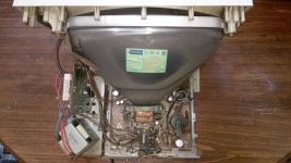
Opened case showing tube, model Matsushita 310 JY B31 (N), power/audio PCB (left), transformer (bottom left) and CRT PCB (middle/right):
IMAG3401.jpg

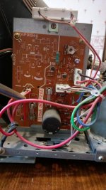
View of the CRT PCB (model TNP81894) showing the variable resistors:
IMAG3406.jpg

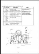
And as luck would have it, this particular CRT PCB, is fully documented in the Panasonic JD 700 & 800 series computer service manual that can be found on bitsavers - Panasonic_JD_700_800_Series_Service_Manual.pdf

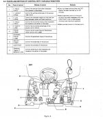
Figure 5-3 in this manual shows the adjustment variable resisters:
Fig 5-3, TNP81894 Adjustment Points.jpg

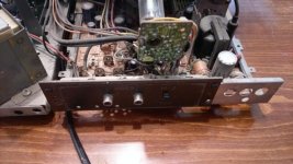
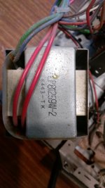
Just for completeness, here are pics showing the model numbers on the power/audio PCB (TNP91946) and the transformer (LP81259W-2):
IMAG3412.jpg IMAG3413.jpg

I'll try adjusting the H-Hold variable resistor once I've cleaned all the dust out. Thanks guys.
 

Attachments

  • Fig 5-3, TNP81894 Adjustment Points.jpg
    Fig 5-3, TNP81894 Adjustment Points.jpg
    10.1 KB · Views: 1
Last edited:
Back
Top