• Please review our updated Terms and Rules here

Motorola 6845 - Which deployment looks best?

CommodoreZ

Experienced Member
Joined
May 18, 2007
Messages
180
Location
Z Labs.
Greetings. I've been reading up on the usage of the MC6845 CRT Controller, and I was amazed at the wide variety of machines that put this chip to use. Most deployments generate simple composite video output for use with generic monitors and televisions. Some tend to use them with TTL CGA monitors, and a few others have integrated video hardware.

Each deployment uses a different set of timing values that are pulled into the 6845's registers and usually left alone (Sanyo MBC-555 not withstanding). However, I haven't seen most of these systems in action long enough to know how well they generate NTSC composite, so I need your collective experience here. Given the chance, I would sit down with an oscilloscope and take notes on the timing of at least a dozen different example machines, but that isn't exactly in the cards. Two questions:

Which machine used it in a way you think looked "best"? I realize this is subjective, but I'm fine with that.

Which machine conformed best to NTSC in terms of timing and frame size?


My goal is to have a good reference point of which composite video signal played nice with a wide variety of display hardware. I've been playing around with providing composite video output on a Heathkit H-19 terminal, but the timing was designed to work with Heathkit's own video hardware, which isn't exactly NTSC compliant. I've been looking up the timing information from documentation of the common ones with the goal of programming my own custom set onto EPROMs. Here are the hex values used on a handful that I've read up on:

Code:
Register		                H19	MDA	Videx	Hercules
R0	Horizontal Total	        60  	61	82	61
R1	Horizontal Displayed	        50	50	50	50
R2	H-Sync Position	                54	52	64	52
R3	H-Sync Width	                8	F	29	F
R4	Vertical Total	                19	19	1B	19
R5	Vertical Scan Line Adjust	4	6	8	6
R6	Vertical Displayed	        18	19	18	19
R7	V-Sync Position	                19	19	1A	19
R8	Interlace Mode	                0	2	0	2
R9	Max Scan Line Address	        9	D	8	D
R10	Cursor Start	                48	B	E0	B
R11	Cursor End	                8	C	8	C
Edit: The H19's 6845 uses a clock of 1.536MHz
 
Last edited:
The only 6845 machine that generates NTSC output that I'm familiar with is the CGA, so I can't answer the "best" question. However, I can comment on how to decide on 6845 register programming in order to best conform to particular timings.

First you need to know (or decide on) the character clock input to the 6845, since that's the basis for all the timing. The CGA has two possible 6845 clocks (1.789MHz and half of that or 895kHz). The sync pulse timings are the same in both modes, but the horizontal counts are doubled with the faster clock.

NTSC has a nominal line rate of 15734kHz (227.5 color carrier cycles). Assuming an 895kHz input clock that gives us 56.875 character clocks per scanline. The 6845 can only do an integer number of characters per scanline, so we'll round that up to 57. This is our horizontal total, but we have to subtract one before programming, so the R0 value is 0x38.

NTSC has a nominal field length of 262.5 scanlines. Most home computers that used the 6845 generated a non-interlaced signal, so 262 scanlines per field (==frame). The 6845 can generate an interlaced signal if you prefer (and don't mind putting up with 30Hz flicker). The total number of scanlines is (R4+1)*(R9+1)+R5 so you can pick whatever register values you like as long as that total is 262. For an interlaced signal I'm not sure offhand if the CRTC adds or subtracts half a scanline (i.e. whether it needs to be programmed for 262 or 263 scanlines) - some experimentation is required.

The position and width of the sync pulses are computed similarly (by looking at the NTSC timing specifications, and rounding to the nearest character position). However, the 6845's model of horizontal and vertical sync is much simpler than NTSC's - it doesn't take into account blanking, a color burst or the fact that the vsync pulse is supposed to be 3 scanlines (some 6845s let you set the vsync height with the high 4 bits of r3 but MC6845 fixes it at 16 scanlines). So if you want to generate a really compliant NTSC signal you need hardware external to the 6845 to deal with those things (like the CGA card has).

Having said all that, I wouldn't sweat the exact timings too much - I haven't seen any 15kHz monitors that can't cope with the CGA's 15.7kHz line rate or 59.92Hz frame rate even though they're not quite to standard. Much more important to get right are the voltage levels: sync, blanking, black, white and the color burst amplitude. CGA (especially the older cards) are quite bad at this (especially in 80-column mode, where the color burst gets truncated) and it causes quite a bit of colour variation between different monitors and capture cards depending on how they treat out-of-spec signals.

What is the character clock rate of your H-19, and how many scanlines per character do you want? With that information I can tell you the CRTC register values which will best approximate an NTSC signal.
 
reenigne: The H19's 6845 uses a character clock of 1.536MHz

Chuck(G): I was unaware of that. Mine is marked MC6845P, R1A8202
 
Okay, the line rate is 15.734kHz so the closest we can get is 98 character clocks per scanline (15.673kHz). So R0==0x61. The sync pulse is 4.7us or 7 character clocks (so R3==0x07) which gives us 4.56us which is a little out of spec (should really be within 0.1us).

I see from http://terminals.classiccmp.org/wiki/index.php/Heathkit_H19 that the H19 normally has 9 scanlines per character row, so that gives us R9==0x08, R4==0x1c, R5==0x01 for 262 scanlines. The same page says that it normally has 80x24 characters so that gives us R1==0x50, R6==0x18. That gives us 9*24 == 216 active scanlines which may be a little on the high side - if it's not possible to adjust the vertical position so that all rows can be seen it might be necessary to reduce the number of scanlines per row and/or the number of rows.

Set R8==0x00 for non-interlaced operation or R8==0x01 for interlaced sync. The MC6845 also supports an "interlaced sync and video" mode (R8==0x03) which lets you have twice the number of character rows but comes with some restrictions (R9 must be an odd number according to the datasheet).

The cursor scanline registers are up to you really. For a CGA-like cursor you might program R10 and R11 to 0x07 and 0x08 respectively (lowest two scanlines lit). You can also try 0x27, 0x47 or 0x67 in R10 to adjust the blink characteristics.

That leaves the two sync position registers R2 and R7. These have to be adjusted to center the image on the screen horizontally and vertically respectively. You want R1<=R2<=R0+1-R3 so that gives you a range of 0x50 to 0x5b. Start with R2==0x55 and tweak as desired. Similarly for the vertical R6<=R7<=R4+1 so 0x18 to 0x1d, so try R7==0x1a initially.

I'll be interested to see how well those work!
 
I'd be telling you the results of my initial tests, but I seem to have hit a bit of an unrelated snag. I think I have a short somewhere on the 5V rail of my terminal logic board, so I have my work cut out for me. When that's cleared up, I'll be able to test the custom ROMs I burned today. Here's what I put on the ROM starting at FFD9:
Code:
R0      61
R1      50
R2      55
R3      07
R4      1C
R5      01
R6      18
R7      1A
R8      00
R9      08
R10     07
R11     08
 
My 1981 Moto Databook lists 6 different versions, but there were more than that. 3 groups of 2 for 1.0, 1.5 and 2.0 MHz (6845, 68A45, 68B45) and then a *1 version of each which contain extra bits for sync pulse width for vertical (R3) and differing meanings for the R6 (interlace and skew) register.

But there are other differences between manufacturers. Details
 
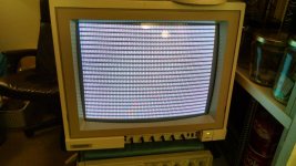
After spending FAR too much time sorting out EPROM and power regulator issues, I have successfully tested the set of variables provided here, and they work well enough within NTSC tolerances for two different CRTs to accept the signals no problem, and for a cheap projector to show the video signal (as well as it can).
IMG_20160327_221110154_HDR.jpg

Thank you very much for the help, I think this will work for the time being. The only glitch I can see is that the very last row of pixels on lower cased j's, g's, p's, and q's are not visible.

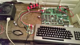
Oh, and for the sake of curiosity, here's the stand-alone H19 board running the ROM. I tested it on my complete H89 first, then moved onto the stand-alone project.
IMG_20160328_044903068_HDR.jpg
 
The only glitch I can see is that the very last row of pixels on lower cased j's, g's, p's, and q's are not visible.

Interesting - sounds like the character ROM is set up for 10 or more scanlines per character row. If you redo the calculation with r9=9, you'll get 240 active scanlines which means you'll get the top and/or bottom of your image cut off and/or will have to reduce the number of rows.
 
Back
Top