• Please review our updated Terms and Rules here

My Rusted PET8032 with busted CRT ...continuous resurrection

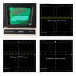
The electron gun within the CRT provides a single spot of light in the centre of the screen (when it strikes the phosphor at any rate).

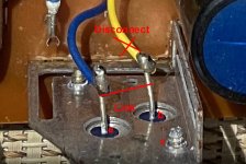
The electron beam is deflected in the horizontal and vertical directions EXTERNALLY to the CRT by means of the scan coil assembly.

As Hugo says, the fact that you get a horizontal line is very good, as it demonstrates that the CRT is working with the PET electronics OK. The horizontal deflection electronics is also working fine. This is also responsible for the internal high voltages to the CRT.

I, personally, would have done a few checks before swapping the CRT over, as you could have damaged both the PET monitor electronics AND the CRT in the process! It seems lady luck is on your side today!

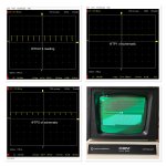
Turn the brightness potentiometer all the way down to dim the line for now and don't operate the monitor for too long like this. The line will be bright, as it is not sweeping the whole screen but the same part of the screen over and over. You could damage the phosphor if you operate it for too long like this.

Ah, but you say you can't adjust the brightness... I wonder if you can't adjust the brightness enough to compensate for the fault, rather than not at all?

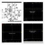
There are three signals from the PET logic board to the monitor - HDRIVE, VDRIVE and VIDEO.

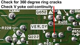
We know HDRIVE is OK (as you get a horizontal line). Can you check for activity on VDRIVE. It is most likely present, but let's be sure. You can do this test with the monitor disconnected.

The vertical deflection electronics within the monitor is very simple.

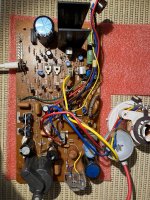
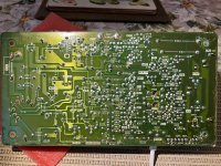
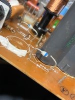
Can you post a photograph of the PET monitor board so we can lookup the schematics for it.

Dave
 
Last edited:
i need to study more the CRT schematic as I have no idea where to start. The intensity of the bright line in the middle of the screen worries me ...is the crt driven too much ?, etc...

Well, you should turn the brightness control down as far as it can go, while fault finding it, and not leave it like that for too long, or it could de-sensitize the phosphor in that area. It might be that the control is out of range to shut the CRT beam current, even when set to minimum, as the beam energy is concentrated in one line.

The vertical scan is created by current in the vertical yoke coils, that are two connections, from the yoke on the neck, to the pcb.

The circuit that drives the V scan coils creates a sawtooth shaped current to deflect the CRT beam on the vertical axis. The start of that scan, at the top of the raster scan, is started from the vertical drive signal (or V sync signals in some sets). In any case, the entire amplifier which drives those vertical coils is not a lot different in its architecture, than the audio amplifier, in your typical sound system, except that it has a much lower low frequency cut off point around a few Hz. It simply amplifies a sawtooth like wave to apply to the vertical deflection coils.

To fix these things, it simply requires a scope to traces the waveform through the vertical amplifier. But a lot of the time it is much simpler and it is something like a power supply failure to the circuit, open circuit fusible resistor etc, So check the voltages in the V scan circuit.

(one thing you can do if you cannot extinguish the beam and it looks like it might be damaging the CRT phosphor, with the bright line, you can disconnect one of the CRT's heater connections, that will kill the electron emission, until you fix the V scan fault).
 
Last edited:
I have slowed down on troubleshooting this 8032 CRT due to the holidays, etc.
The whole 8032 CRT case assembly is dotted with some rusts that I had to use a rust removal on the metal cases before I re-install again and try the tube replacement ( I put it back into it’s original composite monitor case).
I am encouraged by the advises above that I will try to steal the tube and re-install it again on the 8032. Hoping that the board ( vertical circuit can be fixed). Here is a picture of my CRT board
 

Attachments

  • 1086D3B0-5EBC-4BB0-85B6-DDE114E7817A.jpeg
    1086D3B0-5EBC-4BB0-85B6-DDE114E7817A.jpeg
    3.5 MB · Views: 11
  • 86EF44B3-6516-4350-ACFA-0E33D71936CE.jpeg
    86EF44B3-6516-4350-ACFA-0E33D71936CE.jpeg
    4.3 MB · Views: 9
You should be able to diagnose the problem on the PET monitor vertical deflection circuitry without the CRT even.

Hugo, do you think this is possible? I think it should be...

Dave
 
You should be able to diagnose the problem on the PET monitor vertical deflection circuitry without the CRT even.

Hugo, do you think this is possible? I think it should be...

Dave
Yes you can, the only thing is the EHT / anode cap, would require very good insulation, you could put it into a small glass jar and tape the wire so that it cannot slip out of the jar, while you are working. For example if it arced over the the pcb, many transistors would be destroyed.

Since the EHT and high auxiliary voltages (for the CRT A1 anode and focus electrode & video amp etc) are seldom linked in any way to the vertical stages, probably a better method would be to completely disable the EHT circuits, it would likely be safer. This can be done easily by disconnecting(un-soldering) the yellow wire feeding the base of the H output transistor (HOT), and insulate the un-soldered yellow wire so it cannot touch anything and link the transistor's base to its emitter...see attached photo. This disables the entire high voltage and EHT generation and H scan because the HOT remains off.

The vertical scan circuit looks pretty straight forward, the two output transistors that drive the V yoke coils are Q651 and Q652, these have the small aluminium heat sinks on them.

(Do we have the exact schematic for this set ?.......if so can we re-post the link ?)

In any case, it pays to check the simple things first.

One problem, with photos of a pcb, the lighting can make it look like there are ring cracks around pcb pins, when there are not, but still it pays to check. The obvious other things are to check the continuity (measure the resistance) of the V yoke coils, the brown and yellow wires that lead from the VER.DY connector to the yoke's V scan coils, and check that the vertical stages are being powered, as initial steps, in the fault finding.
 

Attachments

  • ringcracks.jpg
    ringcracks.jpg
    334.9 KB · Views: 4
  • DisableH.jpg
    DisableH.jpg
    260.8 KB · Views: 4
Last edited:
Thanks Dave / Hugo...
I will do your advice and also do a good cleaning (IPA) of the pcb assembly ( it is still as is when it came from seller, check the solders and maybe even reflow any point of suspected cracks or cold solder.

A link to the schematic would be very useful. I have the one at Zimmer’s
 
The parts layout should be here: http://www.zimmers.net/anonftp/pub/cbm/schematics/computers/pet/8032/321449.gif.

The schematic should be here: http://www.zimmers.net/anonftp/pub/cbm/schematics/computers/pet/8032/321448.gif.

You will notice circled numbers on the schematic. Numbers 3 through 12 are relevant for the vertical drive circuitry.

The dc voltage levels (where shown) should indicate what a multimeter should read (on a dc scale). The circled numbers relate to the oscilloscope traces and settings as identified within 321450-nn.gif where nn is 03 to 07 for the vertical drive circuitry.

Remind me, do you have an oscilloscope or not?

Dave
 
Also, check, with the meter the 1 Ohm resistors, R655 and R656 on the schematic, which are 1 Ohm resistors (Fusible type I think) that are in series with the emitters of the two vertical output transistors Q651 & Q652. They might be open circuit.

Also check the Blue Tantalum capacitor, C601, with the meter, in case it is shorted out (not uncommon)
 
Last edited:
Thanks...I will update once I got it setup again on my workbench. I put it aside as I was busy assembling a 4x16K Atari800XL Cartridge and compiling and programming the Game(X).bin file to eproms.
I have multimeter(s), logic probe and a cheap USB Hantek 6022B (20Mhz) scope. I will try to scope and measure voltages, compare it with the trace pics from Zimmers and take some snapshots...
Might be done after the New Year as family chores are getting busy.

Happy New Year
 
Sounds like the deflection yoke isnt getting any signal, check its connections first.
Last time I installed the tube (hoping to be compatible one), my observations are I get a very bright line in the middle. Now I could align the horizontal line properly by rotating the Yoke and tightening it so it won't rotate. However, the bright line can not be dimmed or adjusted to have a vertical height deflection.
 
What Clint is saying is that there are two (2) separate deflection coils in the yoke. Horizontal and vertical. Each deflection coils has two (2) separate coloured wires connected to a connector. He just wants to make sure that the vertical deflection coil connector (where it plugs into the PCB) is ok.

In fact, you could check with a multimeter set to resistance (with the power off of course) to make sure that the vertical deflection coil is not faulty (i.e. not open circuit).

Dave
 
Hello...one more for 2022

So I followed the advises from above.....
1. Re- mounted the ‘replacement’ tube, checked all connections... —> still getting the bright line in the middle.
2. Started setting up for diagnostics ( scoping, continuity and voltage readings). I scoped and did a snapshot of the readings into the CRT connector. At first I was not getting any waveform but a straight line signal from the Vertical input. I am not getting scope signals as pictured from Zimmers gifs.

- - then something popped in my mind —> Put back the original CRT Controller HD46505 chip....was surprised to get the boot message displayed but the raster background could not be adjusted no matter what I do with the Vertical pots. See picture
- - However, I am confused since the first CRT controller 6845 worked well with my composite video adapter. Why does it NOT show the same boot message display with the CRT.

3. I also took some readings of the Test Points (TP1 and TP2). The focus of the characters is at max..still blurry.

At this point I have no idea how I can make the raster background disappear. As for the width, I need to get the plastic hex tool to adjust the Choke (coil) marked Width on the PCB.
- - should I start sourcing for capacitors? Transistors?
 

Attachments

  • 80851C84-76EA-462C-8C46-449DEF9E9446.jpeg
    80851C84-76EA-462C-8C46-449DEF9E9446.jpeg
    1,023.5 KB · Views: 11
  • 7DBEF1B6-7F9A-4DD1-9BAE-57FEB6DE8130.jpeg
    7DBEF1B6-7F9A-4DD1-9BAE-57FEB6DE8130.jpeg
    792.2 KB · Views: 11
  • 4E577BAF-E1F7-40CC-9EC4-E1EC19415B46.jpeg
    4E577BAF-E1F7-40CC-9EC4-E1EC19415B46.jpeg
    949.6 KB · Views: 11
Last edited:
So now everything has changed and your vertical scan is working just fine and we have simply moved to a completely different problem where you cannot lower the CRT brightness...is this what is happening now ?

The vertical pots won't set or affect the raster background brightness, that is what the brightness control is for, it adjusts the CRT's beam current and controls the negative voltage on the g1 grid of the CRT.

If you look at the labels on the two pots in the vertical scan system, they affect the scan height and the V scan linearity, nothing to do with the raster brightness.

If that is the case, and it is a brightness issue, you need to check the -155V supply that is used to bias the CRT's grid. It comes via D754 and is connected to filter capacitors, and a resistive divider with a brightness pot , a series resistor and another filter cap C253 onto the crt grid. Measure the negative grid voltage (on C253) with the brightness as low as it will go.
 
So what CRTC did you put in there?

There are some controllers that are supposed to be compatible, but don't actually work in a PET! One day I must find out why...

I had a similar thing with UARTs once and never got to the bottom of that. I just gave up and used the 'original' Intel part instead of the NEC 'copies'.

@Hugo Holden has got the brightness issue issue covered...

Yep, buy the correct tools - otherwise you will crack the ferrite core and have to source a new inductor...

Before you do that (however) have you measured the DC voltage rail out of the onboard regulator? It may be a bit low? It should be 18Volts DC.

Dave
 
Last edited:
Hello,

Dave: I re-installed back the original HD46505SP CRT controller......and yes, there is 18V on the CRT board.
Hugo: Following you advise, there is no -155v at the diode you mentioned above. In fact when I touched it the diode split into two (see pic). So I took the PCB out again, and tried to find a replacement diode....but while looking at the pcb, all of these diode types started splitting minus 1 (they must have been damaged when reflowed the pcb ??) . I pulled some diode from the donor monitor and used them but somehow, it did not work... all I get is squiggly lines scrolling on the display.

Do you guys know the specs on the diodes as I can not find a parts list at Zimmers. By googling for high voltage diodes, it looks like these are close to 1N5625 TR by Vishay rated at 3A/400volts. The fact that what I pulled out from the other monitor maybe not right as I don’t get a proper display.
 

Attachments

  • 88295821-76A1-4F4A-85BC-7624B2FAEEBE.jpeg
    88295821-76A1-4F4A-85BC-7624B2FAEEBE.jpeg
    1.4 MB · Views: 4
I replace those diodes with a BY448, because they out spec the originals and it pays to have a few on hand for general repairs, so buy 10 or more BY448's. If you come across versions of these sinterglass diodes with thicker lead wires of >1mm dia they are higher current carrying types, replace those with the BY228.

You need to replace the others like this too, you can see corrosion infiltrating the body around the wire where it enters, they will soon disintegrate and the wire detach.

D754 being broken, would certainly explain why you could not extinguish the CRT's beam.
 
Last edited:
Back
Top