• Please review our updated Terms and Rules here

NEC Multisync 3D Switching Regulator Unit Dummy Load Resistor / Stuck at Trouble Shooting

TamaMan

Experienced Member
Joined
Sep 29, 2019
Messages
69
Location
Finland
Dear Forum Members,

This is a continuation post regarding my previous post about the required dummy load resistor.

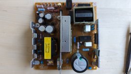
With my dummy load resistor, I am still getting the same in-circuit measured results when trouble shooting (PDF page 31, 2-1 THE SWITCHING REGULATOR UNIT FAILURE) as without any load.

Here's the specs for the required resistor network from the service manual:
figure.png

My dummy load resistor is
K1 -> K4: AX9W 820R + AX9W 820R
K2 -> K4: ROYAL 162 P 5W 2K2 J
K3 -> K4: 10W22OhmJ + 10W22OhmJ

With the dummy load resistor connected to, the measured resistances are
K1 -> K4: 1.558k
K2 -> K4: 2k
K3 -> K4: 44 Ohm

and for comparison, with the MAIN PWB connected:
K1 -> K4: 47.8k
K2 -> K4: 46.1k
K3 -> K4: 879 Ohm

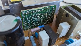
and here's a recap of some in-circuit, trouble shooting flow related measurements:
  • 0V across any combination between K4-K1
  • Steady +17V across pins 13 and 16 of IC601.
  • Voltage across + and - terminals of D601 is +325V (no mention in the service manual what this should be, with my input 230VAC this is OK? RMS?)
  • R603 should be OK (~68k in-circuit)
  • R630 should be OK (~47k in-circuit)
  • R610 should be OK (~0.4 in-circuit)
  • R616 and R617 should be OK (6.9 in-circuit)
  • Fuse F601 is OK.
  • R624 should be OK (~69 in-circuit)
  • R627 should be OK (2,2 in circuit)
  • R601 should be OK (~15 in-circuit)
So before I start to de-solder parts off the board, can someone confirm that my dummy load resistor is OK? Thanks!
 
That table simply lists the range of resistances needed to properly load each output. Ignore the in circuit resistance since that isn't what matters. If you try to run the power supply without the proper load, you'll either get invalid results, or possibly damage it. Your load for the 24v isn't correct.

Based on your voltage measurements, the power supply isn't running at all. Start by looking for obvious problems like shorted semiconductors, and bad capacitors,
 
Thanks for the answers.

tb_21_swregunit.png

So far I've just done some visual inspection and tried to follow the above trouble shooting flow but now would need help with

A) confirmation that my dummy load resistors are OK?
B) any other tips on how to proceed as the above flow seems to end only assuming that R601 is burnt out?

Thanks!
 
That table simply lists the range of resistances needed to properly load each output. Ignore the in circuit resistance since that isn't what matters. If you try to run the power supply without the proper load, you'll either get invalid results, or possibly damage it. Your load for the 24v isn't correct.

Based on your voltage measurements, the power supply isn't running at all. Start by looking for obvious problems like shorted semiconductors, and bad capacitors,
I may have gone through all the components before but I'll do it again. Thanks!
 
Some pictures of the SW.REG.unit. This is the PWE-270A variant compatible with JC-1404HMEDs.
 

Attachments

  • PXL_20230922_065343650.jpg
    PXL_20230922_065343650.jpg
    791 KB · Views: 7
  • PXL_20230922_065415592.jpg
    PXL_20230922_065415592.jpg
    1.8 MB · Views: 7
  • PXL_20230922_065356152.jpg
    PXL_20230922_065356152.jpg
    1.6 MB · Views: 7
He apparently has a pair of 10 watt 22 ohm resisters in series, and the resulting 44 ohms falls within the recommended range of 48 to 24 ohms. Don't see a problem there.
You're right, I misread the part list.

How far through the flow chart? If you make it to the end of the flow chart, you're not seeing any voltages in the power supply, which pretty much means the line fuse, or fusible resistor R601 has to be open. Trouble shooting switching power supplies can be one of the hardest repairs, particularly these old designs with a lot of discrete components.

It's either not starting up, or it's immediately shutting down. Do you see any output voltages, even briefly?

I would start by confirming Q603 isn't shorted, and that none of the low value resistors on the primary side are open. If that's fine, then I'd look around IC601 which provides the drive signal to Q603. Is the IC getting power on pin 16?

I assume you've already checked or replaced the capacitors. I don't see anything obvious, but look for signs of leakage. The small caps can dry out and cause all kinds of problems.
 
In the current state, all the way through with "NO" to all paths.

For path "The voltage across IC601 pins 13 and 16 measured between 1V and 9V", my DMM gives a steady +17V.

And for path "The voltage across + and - terminals of D601 is approx.", my DMM gives +325V.
(Is the service manual missing the expected approx. value here?)

I'll try those tips by andy and report back. Thanks!
 
Looking at the datasheet for IC601, 17v is borderline for it to start, but it probably will. I would be tempted to try replacing IC601 because it will eliminate a lot of possibilities, and is the only part that can't be easily tested.
 
I guess there must be more varieties of MultiSync 3D than I thought, or maybe it's regional. My 120-volt JC-1404HMA-1 came with a Delta supply that looks totally different.

Once you get the set running, if you have to pull the mainboard, check the caps near the LA7835 vertical deflection oscillator. They placed two 100µF/35V aluminum electrolytic caps inside the heat sink so they just get baked. Both of mine had leaked badly. I also had some dramatic leakage on the neckboard.
 
I'm afraid a lot of the time, the flow charts are not worth the paper they are written on, they were designed by people who "imagined certain fault conditions" and they don't take into account many other variations that occur in reality, though they were primarily made to try to assist people with a limited understanding of circuit theory. But a lot of the time, because of the limitations of them, a technician will fall off the bottom of the flow chart.

The main thing repairing an SMPS, is to understand how the circuit works, and set up a test system where safety is the number 1 priority, because you often need to test things on the line side of the supply, in many cases where the circuit is powered. The over 300V DC on the main storage capacitor is potentially lethal too, so the utmost care is required.

There are some un-powered parts tests you can do though such as on diodes & resistors and in circuit capacitor ESR testing. And check the continuity of the inductor L601 (depending on the design, sometimes these small inductors can go O/C)

Don't go willy-nilly replacing parts on hunches they might be defective, only replace a part if there is reasonable evidence on testing that the data supports the part is defective. Or you will create a real mess and probably introduce more problems and fail to repair it. You will see this sort of thing happen a lot with blind parts replacements.

One good bit of news, this VDU has an excellent manual with good schematics and waveforms too.

The first thing before powering it for tests, is to power it via an isolating transformer. The actual common voltage reference for everything on the primary side is the negative terminal of the output of the bridge rectifier and main filter capacitor, so if you want to scope anything like the drive to the output mosfet (gate voltage) or its drain voltage driving the transformer primary, that is where the scope's earth clip would connect to the negative terminal of the bridge. And unless you have a scope with completely isolated inputs (like the TEK 222ps) then you have to power the board via an isolating transformer, you cannot otherwise place the scope's earth clip there. Also, if you look at the drain voltage on the mosfet it is 580v pp, so you cannot use a x10 scope probe, there are only good to around 400v, You need to buy a x100 probe, rated at 1500 to 2000v , these are cheap now on the bay.

There are a number of possibilities why the supply could be shut down. And the IC's internal oscillator not running.

If you look at the start up circuit, the IC is initially powered via R603 and R630, probably to the tune of around 17V that you measured. Then (if the IC is driving the output mosfet and all else was normal) the 18V supply derived from the transformer and Q601 takes over. That is obviously not happening. This implies that the mosfet has no gate drive, or is open circuit, or the current sensing resistor in its source connection R610 is open circuit (check that on the meter, unpowered test). Also the + supply to the transformer primary comes via R602, R624, D605 and R827, if any of these were open that would also result in loss of energization of the transformer and have the equivalent effect of an open mosfet or open R610 or no gate drive for that matter.

(To test the mosfet itself, ideally that is removed and set up in a simple test circuit with a load, a simple low wattage, 5 or 10W auto lamp works and a 12V supply, the source connected to negative, the lamp in the drain to supply positive and place a 1meg resistor in series with its gate and check when the other resistor terminal connects to +12v the lamp turns on and when connected to negative it goes off)

If all those parts are ok, then to confirm that the IC is in shut down mode more likely (or possibly failed), requires a powered test and the scope/isolation transformer to look at the drive waveform at the gate of the mosfet or on pin 2 of the IC.

If the drive waveform is absent, this does not mean that the IC is definitely defective. Apart from receiving the current sense signal developed across R610, it also can be shut down via feedback from two optocouplers monitoring two of the output rails.

So, check the basics first, on passive unpowered tests. In circuit test on resistors for example, the value should never read significantly higher than the marked value, though it may often read lower due to other pathways in the circuit. If those tests reveal nothing definite, then the powered tests with the isolation transformer and scope with the x100 probe are indicated.
 
I guess there must be more varieties of MultiSync 3D than I thought, or maybe it's regional. My 120-volt JC-1404HMA-1 came with a Delta supply that looks totally different.

Once you get the set running, if you have to pull the mainboard, check the caps near the LA7835 vertical deflection oscillator. They placed two 100µF/35V aluminum electrolytic caps inside the heat sink so they just get baked. Both of mine had leaked badly. I also had some dramatic leakage on the neckboard.
Have not yet pulled the main pwb, visually all caps near IC402 and on the CRT pwb look good. I'll check them if I ever need to pull the main pwb, thanks for the tip!
 
Thanks Hugo for the detailed answer. It's good to get others thoughts regarding the trouble shooting flow. I initially though it could be just blindly followed and the root cause would surface.

Currently I have an UNI-T UT61D (CAT IV 600V, CAT III 1000V) DMM that I got for measuring G2 (my 3D takes some time for G2 to drift to an optimal value, T505/F.B.T. going bad?) and have been powering it up with an APC SurgeArrest E10 surge suppressor just so that I don't have to touch the device when powering up/down.

I will start the unpowered tests hopefully this weekend. In any case, I'll report back here.
 
Last edited:
An intermediate update. Some unpowered, in-circuit measurements below. Both Q601 and Q603 produce high resistance and no continuity via their pins. I am assuming that my DMM detects continuity with low resistance parts and depending on the circuit. Next I will visit the local electronic parts shop to prepare testing of the removed Q601 in a test circuit decribed by Hugo previously.


PartMeasurements
Part description from Service Manual
L60127.5, NO CONTINUITYSHIELDING COIL 222K
R6100.2, CONTINUITY0.22H 5% 1W METAL
R602161, NO CONTINUITY1K 5% 1/4W CARBON
R62469.4, NO CONTINUITY68H 5% 3W METAL
D6050.223V BOTH WAYS IN DIODE MODE, NO CONTINUITYEL1Z
R6272.2, CONTINUITY220H 5% 1/4W, CARBON
R60347.74k, NO CONTINUITY68K 5% 3W METAL
R63038.73k, NO CONTINUITY47K 5% 2W METAL
R6311.2, CONTINUITY1.2H 5% 5W WIRE
 
The DC resistance of the coil L601 might be normal for that coil, or it could possibly be open. Normally the DCR would be lower and a DMM show continuity, unless it is a very small part with a lot of fine wire. You are possibly reading an in circuit value that is giving the 27.5 Ohms. One quick check, without having to disconnect one leg of the coil, is to reverse the polarity of the meter's probes, this reverses the applied voltage from the meter, and see if it reads the same value or not. If there is any doubt, if its a through hole part on single sided pcb, you can easily disconnect one leg for testing with solder wick and free one leg in the hole. This goes for any other two legged part too, if you think an in circuit reading might be suspicious.

Also can you cut the schematic out of the manual and post it on its own as an image to make it easy to see the parts that you are talking about.
 
Last edited:
L601 measures 27.5 and no continuity both ways/directions. It is a small? part located on a separate small pwb (top-left corner on the pwb seen here). I'll try the one-leg approach on this one first.

I have two 3D service manuals, one with great resolution but for the US? 120V 60Hz JC-1404HMA model and one with low resolution and missing details for my JC-1404HMED + PWE-270A (the SW.REG.unit variant). I'll see what I can do and try to add schematics as images in future posts.
If it measures the same in both directions, probably that resistance is normal for that part. If the meter currents were a result of the external circuit to it, often the measurement is affected by the polarity of the test.
 
L601 measures 27.7 Ohms out of circuit. It has a marking "222KC" on top of it. Most likely OK just as expected.

I have been re-measuring unpowered parts and their connectivity with the parts mentioned in the circuit descriptions. No clear suspects found yet. I will start preparing for testing the mosfet.
It is a tad suspicious that D605 measures exactly the same in both directions, since the voltage drop is low and likely the measurement represents the external components. For that one, lift or disconnect one leg of it and repeat the diode mode test.
 
D605 measures 0.466V and 0L with one leg lifted. Perhaps C622 was affecting the measurements?

d605.png

I will continue unpowered tests of all related parts and paths (according the schematic diagrams) as I have not tried that yet. Also I need to order a tester for testing the capacitors in-circuit. A "MESR-100 V2" should suffice?

And also make preparations for testing Q603 as described earlier. I'll report back when some progress had happened.
 
Back
Top