• Please review our updated Terms and Rules here

NEC ProSpeed 386SX

I put the laptop together, did the test above except connected the open PSU block directly into the laptop.

Measuring on same DC connectors, with the PSU plugged into the mains

Unfortunately its preforming like Try #2 above except starting at -0.018, after 4 minutes moved to -0.019, 6 minutes -0.020
7 .. -0.022
8:44 .. -0.021
8:50 .. -0.022
11:11 .. -0.021
still at -0.021 at 19 minute mark

:/
 
I mistakenly used the DC connector output instead of the output that makes contact to the laptop. I did a quick test this morning before leaving
DC output was -0.084
Laptop output was 0.

There is a trigger on the PSU that gets pushed when in the laptop. I'll check that tonight.
 
Hi, tonight I made sure the trigger was pressed, reading floated around negative 0.023 & -0.024, after about 18 minutes it moved to -0.025.

Is it time to test the electrolytic capacitors or does the pattern in these tests suggest a different kind of issue?
Thank you

EDIT after switching off the laptop, the multimeter has the same reading but at -0.028.
 
Last edited:
Thank you both for the help. I will begin trying the electrolytic, I think I should have all the sizes except for the really big one.

If I need to replace the gold / brown ones, are they still that colour and style today?
 
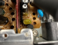
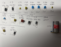
These are the ones I'm a bit confused on. I believe the blue is a ceramic disk, unsure on the gold and little brown types,
Thank you for any clarification.
 

Attachments

  • caps.PNG
    caps.PNG
    526.7 KB · Views: 6
If I need to replace the gold / brown ones, are they still that colour and style today?
Colour can vary.

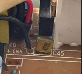
The big brown one that I see in a photo of post #4 is a polyester type. See [here].

The disc shaped brown ones are ceramic. See [here].

These are the ones I'm a bit confused on. I believe the blue is a ceramic disk, unsure on the gold and little brown types,
Yes, the blue one is ceramic.

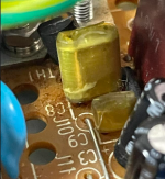
As for the gold/yellow ones, it is hard to tell from the photo, but do they look like the third capacitor (top row, third from left) in the 'Film capacitors' section of [here] ?
 
I've not really delt with capacitors other than small PCB projects, and especially stayed away from ones this size when fixing old computers.

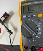
Am I measuring this correctly? I took a photo of my setup.
I discharged with a 22k resistor, connected to the + & - on the board, (I assume this is fine since it only contains the capacitor?)

Multimeter made a single beep then displayed OL.
I moved to DC V and it had a value but the Fluke instructions said OL may mean its bad or I'm using a setting out size of range.

Thank you

220.png
 
I moved to DC V and it had a value but the Fluke instructions said OL may mean its bad or I'm using a setting out size of range.
On the left of the display is a diode symbol. So the meter is in diode-test mode. You need to push the orange button to switch the meter to capacitance mode.

( And check your meter's user manual to see what range of values the meter is capable of. )
 
Thank you for the links, I was actually on that Film Capacitor page earlier today and looking at that one! I did get better pictures just now with that capacitor removed and they do seem to match.small.pnggold.png
 
Last edited:
Oh, thank you, I'll do that.

EDIT: I'm an idiot, I never made the correlation between the orange markings and a button up top. To be fair I bought this used to simply check voltages when I bought a broke computer, learning what all this stuff means lol

It measured 220/222, so one down :)
 
Last edited:
Hi,
I tested all the caps, ink is their marked value and the pencil is the multimeter readings

C80 would not give a reading. I cycled through the ranges incase the AUTO wasn't adjusting, but it was 0.00uf.

I guess all components are important, but would this be enough to halt the power output?
Thanks


caps.png
 
Last edited:
C80 would not give a reading. I cycled through the ranges incase the AUTO wasn't adjusting, but it was 0.00uf.
151 = 15 0 pF = 0.15 nF

The reading is explained by 0.15 nF not being within the measurement range of your meter.
Quote from the manual: "Farads from 1 nF to 9999 μF."
And 1 nF is the best resolution.

( Later, you may want to add a dedicated capacitance meter to your test kit. Its range will be much wider. )

I guess all components are important, but would this be enough to halt the power output?
Putting C80 aside:

For the ones that have three digits:
472 = 47 00 pF = 4.7 nF
104 = 10 0000 pF = 100 nF
222 = 22 00 pF = 2.2 nF
102 = 10 00 pF = 1 nF
151 = 15 0 pF = 0.15 nF
473 = 47 000 pF = 47 nF

Based on that, nothing 'sticks' out to me.

EDIT: I'm an idiot, I never made the correlation between the orange markings and a button up top.
I was quick to respond because I know that meter well. I also have a 115.
 
ah that makes sense.

Well I was hoping a capacitor was the issue. I have no clue where to go next. I will have a look on the motherboard and see if the + wire on the PSU contact goes somewhere else as it uses a different contact from what the battery uses. Maybe there's something there.

Thank you for your help, I have learned a lot from the detailed information in your responses. Really appreciate it!
 
Well I was hoping a capacitor was the issue.
C80 has not been verified yet. It's position in the circuit is unknown, so criticality is unknown.

Capacitors have electrical properties besides capacitance. One is equivalent series resistance (ESR), and in some situations, that property is important. In switch mode power supplies (SMPS), there is often small-value aluminium electrolytic capacitors that support the switching/controller chip. Sometimes, in a faulty SMPS, one discovers the failure cause to be a small-value aluminium electrolytic capacitor - it's ESR has drifted over time to the point of affecting circuit operation, but it's capacitance can still be within the stated +/- 20% tolerance.
The 47 µF cap is pretty much spot on in capacitance, and so it seems unlikely to me that the ESR would significantly change without the capacitance changing also. In the photo of post #32, tape is masking part of the written measurement of the 100 µF cap. Take a chance, and replace both ?

I have no clue where to go next.
There is so much that can go wrong in a SMPS. In the day, an area that I worked for sent faulty SMPS out for repair, because it was economical to do so. The repair company only charged if they fixed the SMPS. The company would have started off with basics like a visual inspection, checking the fuse, checking PN junctions (repeating our simple tests). From what we saw had been replaced, we worked out that the company was fixing a lot by doing a replacement of all aluminium electrolytic caps.

I have seen web sites that provide guidance on the repair of SMPS.

I will have a look on the motherboard and see if the + wire on the PSU contact goes somewhere else as it uses a different contact from what the battery uses. Maybe there's something there.
Yes.

If not fruitful, perhaps try putting a suitable resistive dummy load on the 20V PSU output (i.e. trying to prove the 20V PSU as the problem cause.)
 
Hi,

I was wondering that, if they can read fine but when being used in the circuit not perform as expected.

Thanks for the extra info. Yes, I feared it may be a bigger issue than I can handle.

I do have a pack of dipped capacitors on the way from Amazon.
The 100uf measured 102.
I replaced all the electrolytics except the large one.

I tested to see if anything changed.

Still nothing using the PSU in the PC

When using the charging setup;

There is now a louder hum, maybe a hiss. The measurement stops at around 8.xx. The LEDs on key keyboard are faint, yellow, green, red.

When the PC is turned off, there is still a hiss but faint.


I made a slight dent in the large capacitor trying to get it free from the glue, its not deep but figured I'd mention.


On try 2, no hum, constant -0.010 on the meter, nothing :(


I took a picture of the board. It looks like there is another power circuit? I'll post the pic

I was using it with the alternate source using the DC connector. Do you think its okay to use it this way? Since I probably can't fix the PSU I was thinking I could make the alternate source its dedicated power supply,...... unless that's a bad idea. Its a LongWei 30V/10A DC power supply.
b1.png
Thanks
 
Last edited:
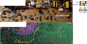
I mapped a piece of the board
Purple shading is the PSU + contact
Blue shading is the battery + contact
Red shading is where they seem to meet.
Pinout is
1+2 "Brown" contact, assume ground
3 not used on either
4 "Yellow" battery only (charging state?)
5+6 "Green", battery +
7+8 "red", PSU +
* flipped the solder side to make positional comparing easier.

frontback.png
 
Last edited:
I took a picture of the board. It looks like there is another power circuit? I'll post the pic
Yes. There has to be something to drop the +20V down to the various smaller voltages used by the mainboard. And some battery charging circuity too.

I was using it with the alternate source using the DC connector. Do you think its okay to use it this way? Since I probably can't fix the PSU I was thinking I could make the alternate source its dedicated power supply,...... unless that's a bad idea. Its a LongWei 30V/10A DC power supply.
I cannot see why it would be a problem.

I mapped a piece of the board
This is "heading down a rabbit hole."
 
oh that makes sense.

Yes, it was fun at first but that faded quickly lol.

I may have to admit defeat until I gain some more experience. I did learn a lot from the attempt though, especially about about capacitors and testing.
Thank you again for all of your help!
 
I did learn a lot from the attempt though, especially about about capacitors and testing.
When I was taught electronics (as a technician, not an engineer), quite often, subjects had two parts.
Example - capacitors:
Part 1. Capacitor theory taught using 'perfect' capacitors, i.e. capacitors that have only one property, capacitance.
Part 2. Real-world capacitors are not perfect. Capacitors have other properties such as resistance and inductance. These other properties need to be considered in various scenarios. Etc.

And safety was very big. If possible, an exam had one or two safety questions. Getting any of those safety questions wrong was instant exam failure.

After the electronics course, more is learnt whilst active in the profession.
 
Back
Top