- VCF South West - June 14 - 16, Davidson-Gundy Alumni Center at University of Texas at Dallas
- VCF West - Aug 2 - 3, Computer History Museum, Mountain View, CA
- VCF Midwest - Sept 7 - 8 2024, Schaumburg, IL
- VCF SoCal - Mid February 2025, Location TBD, Southern CA
- VCF East - April 2025, Infoage Museum, Wall NJ
-
Please review our updated Terms and Rules here
You are using an out of date browser. It may not display this or other websites correctly.
You should upgrade or use an alternative browser.
You should upgrade or use an alternative browser.
Need help - repairing a 12-inch monochrome CRT monitor (Daewoo DM-120MWA)
- Thread starter inv
- Start date

Hugo Holden
Veteran Member
typo the; 845666, should have been typed 84566.
Hugo Holden
Veteran Member
Yes, it is fairly obvious what is going on and I will confirm it tonight.
One thing, although these transformers are called "flyback transformers" they do not transform voltages and currents in the normal manner of a transformer. It is an energy storage and release system, not unlike a Kettering ignition system in a vintage car.
In general, little energy is taken from the secondary when the primary is energized (unless the scan time voltage is rectified and use for some auxiliary application) normally the peak of the flyback voltage tips are rectified to obtain the secondary auxiliary voltages. Not always, but mostly. And when the rectangular part of the waveform is rectified for an auxiliary secondary supply, little energy is normally taken from it.
The time that the transistor conducts, is the time where the primary current that builds up & energizes the core with an energy of L.I(squared)/2 Joules. When the transistor is cut off, the stored energy results in the half cycle of flyback oscillation because the inductance and tuning capacitance forms a resonant circuit that oscillates.
The voltage peak on the primary is when the magnetic energy has been converted to CV(squared)/2 energy of the electric field of the tuning capacitances, and then as the primary voltage attempts to oscillate below zero, the damper diode conducts and returns the core energy to the power supply (or boost capacitor), in a near linear decay of current, similar to the linear rise in the transistor current. Those two currents resulting in a near linear sawtooth current wave.
But, it is fairly apparent with this fault that the transformer is behaving in a "usual transformer mode" as soon as the transistor switches on, due to a heavy load, most likely due to a short on at least one of the secondary windings, or the EHT winding. And there is negligible stored energy in the core, and this is why the damper diode is so easily pushed out of forward conduction by the superimposed oscillations and why primary current flows immediately after the transistor is switched on.
Hugo Holden
Veteran Member
Looking around for possible replacements, at least this particular transformer is fairly characteristic, having a 10 pin base. Most only have 8 pins, the ones labelled 0 & 9 are generally not on the transformer base, but they are on your transformer by the look of the pcb photo ? even though they connect nowhere.
Since we don't have the number of the original part, the first task is to find one with identical dimensions and footprint, the size of the core relates to the size of the CRT. So it will be necessary to ask the sellers to check the measurements, then take a punt and check the transformer after it is received, for similar winding connections and resistances. The inductance measurement comparison won't help much because of shorted turns.
These three looked promising:


But this one with the 10 pin base could possibly be ok, if its dimensions matched.
Since we don't have the number of the original part, the first task is to find one with identical dimensions and footprint, the size of the core relates to the size of the CRT. So it will be necessary to ask the sellers to check the measurements, then take a punt and check the transformer after it is received, for similar winding connections and resistances. The inductance measurement comparison won't help much because of shorted turns.
These three looked promising:
FBC1215AL Flyback Transformer Replaces Samsung HR 81196 | eBay
Find many great new & used options and get the best deals for FBC1215AL Flyback Transformer Replaces Samsung HR 81196 at the best online prices at eBay! Free shipping for many products!
www.ebay.com
SAMSUNG FLYBACK TRANSFORMER FBC-1415CL OEM 2859-087-010 USED IN VARIOUS MODLES | eBay
Find many great new & used options and get the best deals for SAMSUNG FLYBACK TRANSFORMER FBC-1415CL OEM 2859-087-010 USED IN VARIOUS MODLES at the best online prices at eBay! Free shipping for many products!
www.ebay.com
PANASONIC FLYBACK TRANSFORMER TLF80843 USED IN VARIOUS MODELS | eBay
Find many great new & used options and get the best deals for PANASONIC FLYBACK TRANSFORMER TLF80843 USED IN VARIOUS MODELS at the best online prices at eBay! Free shipping for many products!
www.ebay.com
But this one with the 10 pin base could possibly be ok, if its dimensions matched.
Hugo Holden
Veteran Member
I did some experiments on one of my VDU's, monitoring the emitter current and applying various lords to a shorted turn and replicated similar results to your recording.
When all is "normal" the emitter current does not rise above zero until about at least 15us after the transistor is switched on by the driver circuitry, unless there are shorted tuns, then it rises right away.
It does seem fairly certain, in this particular case, that the flyback transformer is defective. But I hate saying that, because in my experience, they are a very reliable part, although most people appear to blame them right away, for no sound reason, when anything goes wrong with a CRT VDU.
I did some experiments on one of my VDU's, monitoring the emitter current and applying various lords to a shorted turn and replicated similar results to your recording.
When all is "normal" the emitter current does not rise above zero until about at least 15us after the transistor is switched on by the driver circuitry, unless there are shorted tuns, then it rises right away.
It does seem fairly certain, in this particular case, that the flyback transformer is defective. But I hate saying that, because in my experience, they are a very reliable part, although most people appear to blame them right away, for no sound reason, when anything goes wrong with a CRT VDU.
Thank you very much, Hugo.
I want to tell you that your help was essential. Not only in figuring out what is the key problem of my VDU, but also in getting a much better and deeper understanding of mine. I enjoyed the process very much. It improved my understanding a lot. I had read many things on the web about how the H output circuit (including FBT) works, but many of these were not clear to me. After this experience guided by your wonderful help, I've just realized that now I can understand what I had read much better.
From the article you mentioned (it was very, very interesting!) and from several other documents on the web, I've learned the principle of the "ring test" or "resonance test" for the Q value of a resonator such as a FBT. So I gave it a try today, expecting another clear confirmation that the FBT is defective. I completely desoldered the FBT from the PCB, and put a small value capacitor to the primary winding (pins 1 and 3), to form an LC resonant circuit. I don't have a function generator, so I used a microcontroller and a buffer chip to produce a square wave, which I used to trigger the resonant circuit. The voltage I produced was limited to 3.3V and the maximum current was about 40mA, and it seemed much weaker than a function generator output. So I thought I had to use a cap of relatively small value (if I understood the principle of the ring test correctly), to make the resonance visible.
In any rate, I ended up with a set up as shown in the following photo.

Initially I tried to couple inductively the square wave with the LC resonator circuit (as shown in your PET article, if I understood it correctly), but it didn't work. Perhaps I did something wrong, or my waveform generator was too weak. So I tried capacitive coupling, as shown in the above photo. After adjusting the capacitor values a few times, I obtained the following:

The amplitude is not exactly exponentially decaying, but I guess it might be because of the quick collapsing. It seems to show that the amplitude decrease to half within at most 2 cycles, so it seems to suggest that the Q factor is very low and FBT is likely to have a shortened winding.
But, I was not completely sure, since this is my first time to do this test... I needed to know what the result should be when the FBT is good, but I had no experience at all. I saw some example waveforms obtained by a ring test for a good FBT on the web. But I was not sure whether my test setup was bad, or the FBT bad, or whether I am interpreting the result properly.
To see whether my test setup actually works, I tried to compute the resonance frequency. Hugo told me that the expected inductance of the primary winding of this FBT could be 200 uH range, and I used a 220 pF cap, so the resonance period was expected to be roughly 2 pi sqrt (LC) = 1.32 us. This seems similar to the waveform shown above. So my test setup was likely to work.
As another attempt, I got another good FBT and did a similar test. I needed to adjust the cap values again, perhaps because this FBT has different inductance (and internal capacitance). In fact this FBT is larger, so the resulting resonance waveform had lower voltage. (I wish I had a better "real" function generator!) In any rate, I obtained the following, by using my setup for a good FBT.

It shows a much higher Q factor, I believe. So perhaps my setup for the ring test is not too bad, I guess. And the test I did above seems to confirm that the FBT is not in a good condition.
I admit that many of the above I said might be wrong, given that this is my first time. So, please correct me if so!
Hugo Holden
Veteran Member
It is interesting when two tuned coils are on the same magnetic core and imperfectly coupled (k<1). Especially in the case of the flyback transformer, where often the EHT winding self resonance is similar in frequency to the tuned primary. The effect is to down-shift the main resonance and a high frequency resonance appears. Typically for a transformer tuned by its original primary tuning capacitor value the two frequencies are around 30kHz and 140kHz without the yoke connected.
The resonance tests I use require a function generator with a solid 10Vpp output, a series resistor and coupling loop and the idea was to test the transformer in circuit, with its usual tuning capacitor present.
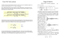
That recording you made where the decay did not appear exponential is the result of two frequencies interacting (attached). As noted in the PET VDU article, this information is not on the web (except for in my article) that I have seen. This information came from a vintage book in my library of pre-ww2 textbooks, Principles of Electricity, Page & Adams, Chapman Hall, 1931. Also, this book contains the full derivation of Maxwell's equations, beautifully done, which demonstrate that an electromagnetic wave travels at the speed of light.
The resonance tests I use require a function generator with a solid 10Vpp output, a series resistor and coupling loop and the idea was to test the transformer in circuit, with its usual tuning capacitor present.
That recording you made where the decay did not appear exponential is the result of two frequencies interacting (attached). As noted in the PET VDU article, this information is not on the web (except for in my article) that I have seen. This information came from a vintage book in my library of pre-ww2 textbooks, Principles of Electricity, Page & Adams, Chapman Hall, 1931. Also, this book contains the full derivation of Maxwell's equations, beautifully done, which demonstrate that an electromagnetic wave travels at the speed of light.
Attachments
Last edited:
Hugo Holden
Veteran Member
.....looking more at the replacement transformer options, I think you should take a punt on the one from Aliexpress on the link on post #24, I think it is likely from the same manufacturer as your original one , it has the same size white paper label on the lower transformer body too and the uncommon 10 pin array.
.....looking more at the replacement transformer options, I think you should take a punt on the one from Aliexpress on the link on post #24, I think it is likely from the same manufacturer as your original one , it has the same size white paper label on the lower transformer body too and the uncommon 10 pin array.
The one in Aliexpress has been changed to "no longer available," so I've contacted the seller. They told me they would recheck their stock. I'm waiting for their response.
Thanks a lot for your additional explanation on the "imperfect coupling." I agree that this is not available on the web other than yours, or is very well hidden. Some explanations I found are for general resonators, not specific to FBTs, so they might have less motivation to discuss it. But even in explanations focusing on the FBT case, they just talk about the decay of primary frequency oscillation, counting the cycles of half-life.
In addition, I've contacted someone in another forum who has the same VDU which is working. In my unit, a label on the FBT that is expected to have the model number is not readable at all, but they may be able to find the model number of the FBT from their unit. It is not yet sure. I will update you when I get a response from them.
Update:
Luckily, from an owner of the same VDU model, I was told that the original FBT label has the following three lines:
MMF-81011
E105192K? (the last letter ? is not clearly identified but looks like a "D")
KFS-20860
Googling does not give an FBT with these model numbers. I also found the website of "HR Diemen" (https://www.hrdiemen.com) which has an interesting database of FBT information, but it does not have anything on these model numbers.
Though, I guess I found something which may be useful. An FBT on eBay (https://www.ebay.com/itm/400908964962), with model number KFS21288, is claimed to be a replacement for MMF-81011. The photo looks very similar to the defective FBT I have. Interestingly KFS21288 has 8 pins only, while my FBT has 10 pins. Because pins 0 and 9 of my FBT are not actually used, I guess this still makes sense. Googling for model number KFS21288 gave a few more results. For instance, another eBay seller (https://www.ebay.com/itm/302146741276) offers a lower price for the same FBT (although I need to pay more than the unit price for delivery). So, I am considering ordering it to give it a try.
Comments will be appreciated, as always!
Hugo Holden
Veteran Member
This is very good news that the transformer has been identified, go for the KFS-21288 from Dalbani on ebay. Or the other one from premiumpartsplus would be fine. Your VDU is almost fixed.
Last edited:
This is very good news that the transformer has been identified, go for the KFS-21288 from Dalbani on ebay. Or the other one from premiumpartsplus would be fine. Your VDU is almost fixed.
I ordered it. I hope the other parts, especially the tube and yoke, don't have any serious problems... I will post an update when I receive the FBT.
Hugo Holden
Veteran Member
Probably unlikely they are faulty too.I ordered it. I hope the other parts, especially the tube and yoke, don't have any serious problems... I will post an update when I receive the FBT.
This VDU is an interesting case in point.
When it is up & running again, make another scope recording of the transistor's emitter current and post it along with the original recording. It will be a good talking point comparing the two waveforms and I think it will help others to test out the flyback transformers in their VDU's and reassure themselves (hopefully) most of the time at least, that the transformer is ok.
Hugo Holden
Veteran Member
........ I would also recommend when you fit the new transformer, make sure the Yoke is re-connected before testing.
........ I would also recommend when you fit the new transformer, make sure the Yoke is re-connected before testing.
Thanks a lot for the caution. When I get a new FBT in my hand, I think doing as follows would be reasonably safe: before starting a test, reconnect all parts in place, but for R618 which was burnt, add a DMM in series to monitor the current. In addition, put another DMM to monitor the power supply voltage drop (if any). Turn on the unit with my fingers crossed and watch the readings, being ready to turn it off immediately if the current or voltage is unusual. Perhaps this seems the best I could do...
When the initial power-on goes well, I will measure the HOT emitter current as suggested!
Hugo Holden
Veteran Member
It would be worth doing a brief check with the Ohm meter on the new transformer to see if the winding configurations are approximately the same, I think they will be.Thanks a lot for the caution. When I get a new FBT in my hand, I think doing as follows would be reasonably safe: before starting a test, reconnect all parts in place, but for R618 which was burnt, add a DMM in series to monitor the current. In addition, put another DMM to monitor the power supply voltage drop (if any). Turn on the unit with my fingers crossed and watch the readings, being ready to turn it off immediately if the current or voltage is unusual. Perhaps this seems the best I could do...
When the initial power-on goes well, I will measure the HOT emitter current as suggested!
I've received a new transformer from Dalbani, KFS-21288. Unfortunately, this new FBT doesn't seem to be pin-to-pin compatible with the original FBT. More details are below.
Ohm meter check on the original FBT shows the following, as I posted earlier (https://forum.vcfed.org/index.php?t...onitor-daewoo-dm-120mwa.1242137/#post-1304169)

In particular, pins 1-4 of the original FBT are primary.
But, for the new transformer, pins 5-8 look like the primary side; a high voltage diode test tells that pins 1-4 are connected to the HV red wire.
Interestingly, ohm meter readings between pins 8, 7, 6, 5 of the new FBT are exactly the same as the readings between pins 1, 2, 3, 4 of the original FBT (note that the pin order is reversed). So, perhaps, one could guess that these two FBTs might have "compatible" primary sides (???).
The ohm meter readings of the secondary side (pins 1-4) of the new FBT are as follows:
These values are different from those of the original FBT shown above. I think comparing the ohm meter readings directly is not the right way, especially because the original FBT has a defective winding. But, even the order of the pins along the secondary winding is not compatible.
From a positive viewpoint, the ratios of the secondary winding ohm values are very similar, as shown below:
4.49 : 0.61 : 1.05 = 100 : 13.6 : 23.4 (original)
2.27 : 0.37 : 0.62 = 100 : 16.3 : 27.3 (new)
So, very very hopefully, the new FBT might have compatible secondary windings which are made with thicker wire... I hope I correctly remember what I learned from my freshman physics course (the most advanced course related to electronics I ever had ^^), that the wire thickness does not change the inductance of a coil...
As another observation, the size of the new FBT is slightly bigger than the original, as shown below (the top is original, and the bottom is new). Perhaps this justifies the use of thicker wire? Their physical pin locations (pitch and radius) are compatible.

.
.
.
Somebody who owns this VDU has confirmed the model number "MMF-81011" on the original FBT. Dalbani's eBay page (https://www.ebay.com/itm/400908964962) says that the new FBT, KFS21288, replaces MMF-81011. I don't understand why the pinouts are completely different, in spite of this information. Could it be that my VDU has a different internal revision?
If it is a reasonable guess, then perhaps, hopefully, could one even expect the possibility that the new FBT might work for my VDU just by permuting the pin connections? I think this might be too wishful...
I didn't do it yet, but perhaps I may try to connect the primary part of the new FBT to my VDU mainboard, with pin numbers permuted, to do the same tests I did earlier. Especially to see whether the excessive current drain is changed to normal, and HOT collector voltage waveform becomes normal. Would it make sense?
Ohm meter check on the original FBT shows the following, as I posted earlier (https://forum.vcfed.org/index.php?t...onitor-daewoo-dm-120mwa.1242137/#post-1304169)
In particular, pins 1-4 of the original FBT are primary.
But, for the new transformer, pins 5-8 look like the primary side; a high voltage diode test tells that pins 1-4 are connected to the HV red wire.
Interestingly, ohm meter readings between pins 8, 7, 6, 5 of the new FBT are exactly the same as the readings between pins 1, 2, 3, 4 of the original FBT (note that the pin order is reversed). So, perhaps, one could guess that these two FBTs might have "compatible" primary sides (???).
The ohm meter readings of the secondary side (pins 1-4) of the new FBT are as follows:
1 ------------ 2 ------------ 3 ------------ 4
   2.27 ohm       0.37 ohm       0.62 ohm
These values are different from those of the original FBT shown above. I think comparing the ohm meter readings directly is not the right way, especially because the original FBT has a defective winding. But, even the order of the pins along the secondary winding is not compatible.
From a positive viewpoint, the ratios of the secondary winding ohm values are very similar, as shown below:
4.49 : 0.61 : 1.05 = 100 : 13.6 : 23.4 (original)
2.27 : 0.37 : 0.62 = 100 : 16.3 : 27.3 (new)
So, very very hopefully, the new FBT might have compatible secondary windings which are made with thicker wire... I hope I correctly remember what I learned from my freshman physics course (the most advanced course related to electronics I ever had ^^), that the wire thickness does not change the inductance of a coil...
As another observation, the size of the new FBT is slightly bigger than the original, as shown below (the top is original, and the bottom is new). Perhaps this justifies the use of thicker wire? Their physical pin locations (pitch and radius) are compatible.
.
.
.
Somebody who owns this VDU has confirmed the model number "MMF-81011" on the original FBT. Dalbani's eBay page (https://www.ebay.com/itm/400908964962) says that the new FBT, KFS21288, replaces MMF-81011. I don't understand why the pinouts are completely different, in spite of this information. Could it be that my VDU has a different internal revision?
If it is a reasonable guess, then perhaps, hopefully, could one even expect the possibility that the new FBT might work for my VDU just by permuting the pin connections? I think this might be too wishful...
I didn't do it yet, but perhaps I may try to connect the primary part of the new FBT to my VDU mainboard, with pin numbers permuted, to do the same tests I did earlier. Especially to see whether the excessive current drain is changed to normal, and HOT collector voltage waveform becomes normal. Would it make sense?
Last edited:
I've received a new transformer from Dalbani, KFS-21288. Unfortunately, this new FBT doesn't seem to be pin-to-pin compatible with the original FBT. More details are below.
...
If it is a reasonable guess, then perhaps, hopefully, could one even expect the possibility that the new FBT might work for my VDU just by permuting the pin connections? I think this might be too wishful...
I didn't do it yet, but perhaps I may try to connect the primary part of the new FBT to my VDU mainboard, with pin numbers permuted, to do the same tests I did earlier. Especially to see whether the excessive current drain is changed to normal, and HOT collector voltage waveform becomes normal. Would it make sense?
Update: I gave it a first try as follows. I connected the new FBT primary side (original pins 1-4) to the mainboard, with the secondary side (original pins 5-8) left unconnected. The HV to CRT wire and yoke were left unconnected. I turned on the unit, and luckily it didn't burn. The readings are as follows:
The current at R618 (the resistor which was burnt because of the high current drain) is 0.165A. Much smaller than the previous 2.4A.
The horizontal output transistor base and collector voltages are as follows:

If I correctly understood how the horizontal output stage works, I guess this result is a promising sign. The waveform has some distortion, but I think it might be because of the disconnected parts (secondary side, yoke and HV to CRT).
I'm not yet sure if it would be safe to do another test after connecting the secondary side (including HV) and yoke...
Last edited:
Update 2: bad news ...
I connected the secondary side, HV and yoke, i.e., everything. The FBT pins are connected as follows:
When I turned the unit on, the CRT neck part started sparking! Because I turned it off immediately (I believe I had to ^^), I couldn't observe the spark carefully, but I think it was inside the CRT neck, to which the small neck board is attached.
I guess that ... perhaps the high voltage generated by the new FBT was too high for the tube... I can't check this because I don't have a high-voltage meter.
Or, by googling I found that it may happen if the tube is cracked (so that the inside is no longer a vacuum). If it is the case, perhaps there may be no way to fix it ...
I connected the secondary side, HV and yoke, i.e., everything. The FBT pins are connected as follows:
new --- original
  1 --- 7
  2 --- 5
  3 --- 6
  4 --- 8
  5 --- 4
  6 --- 3
  7 --- 2
  8 --- 1
When I turned the unit on, the CRT neck part started sparking! Because I turned it off immediately (I believe I had to ^^), I couldn't observe the spark carefully, but I think it was inside the CRT neck, to which the small neck board is attached.
I guess that ... perhaps the high voltage generated by the new FBT was too high for the tube... I can't check this because I don't have a high-voltage meter.
Or, by googling I found that it may happen if the tube is cracked (so that the inside is no longer a vacuum). If it is the case, perhaps there may be no way to fix it ...
Hugo Holden
Veteran Member
Possibly, all is ok with the replacement transformer.
Inside the CRT bulb, is (normally) a near perfect vacuum like space. There are no significant charge carriers in there (except from the emitted electrons from the cathode and a very low number of negative ions), and no significant free gas atoms to ionize. Even the applied voltages were 3 or more times what they should be, no sparks should ever be seen coming from inside the CRT, unless it has had air leak into it. The usual cause for this is a crack in the neck or the glass exhaust tip between the pin array.
Usually though, if the CRT has "let down to air" this reacts with the CRT heater, and it quickly oxidizes (burns out) filling the neck with white smoke. Check the CRT's heater continuity.
The sparking could have come from spark gaps that are integral with the CRT socket in some cases.
The transformer pin connections; generally the normal resistance (referring to your original transformer) between 1 & 3 and 1 & 4 should be very roughly similar, perhaps a little lower between 1 and 4, vs 1 & 3 and between pins 2 & 3 very low.
I would suggest, take the socket off the CRT base for now (leaving the CRT's EHT clip safely connected to the CRT as usual), re-power it (with everything else connected normally) and take a recording of the output transistor's emitter current, and we will confirm first that the transformer is working normally. If so, then we will find you a new CRT, because we never give up.
Last edited: