• Please review our updated Terms and Rules here

Need help - setting up old Shugart 800-2 8inch drive on my freedos testbench

_ds_

Experienced Member
Joined
Aug 30, 2023
Messages
54
Hi All,

I am running into troubles setting up an old Shugart 800-2 Drive from Ebay.
The only good thing is, that the AC (230V - I am located in Europe) works fine.

My setup:
**********
Mainboard: ASUS N68-S3 UCC
OS: Freedos 1.3
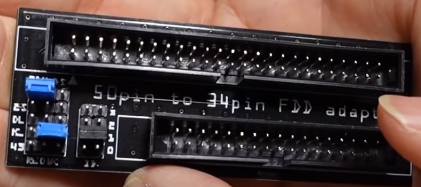
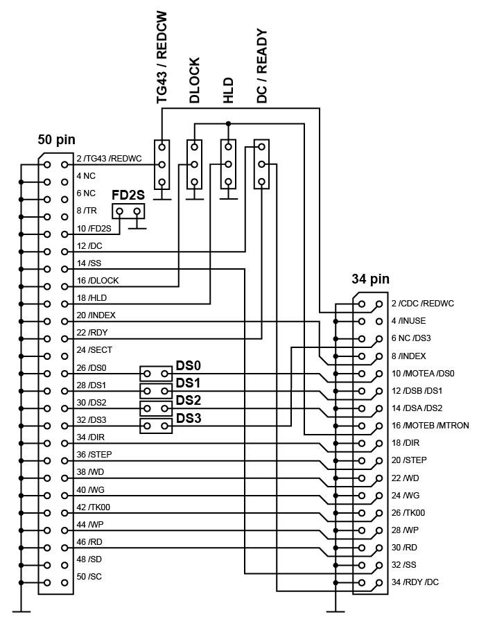
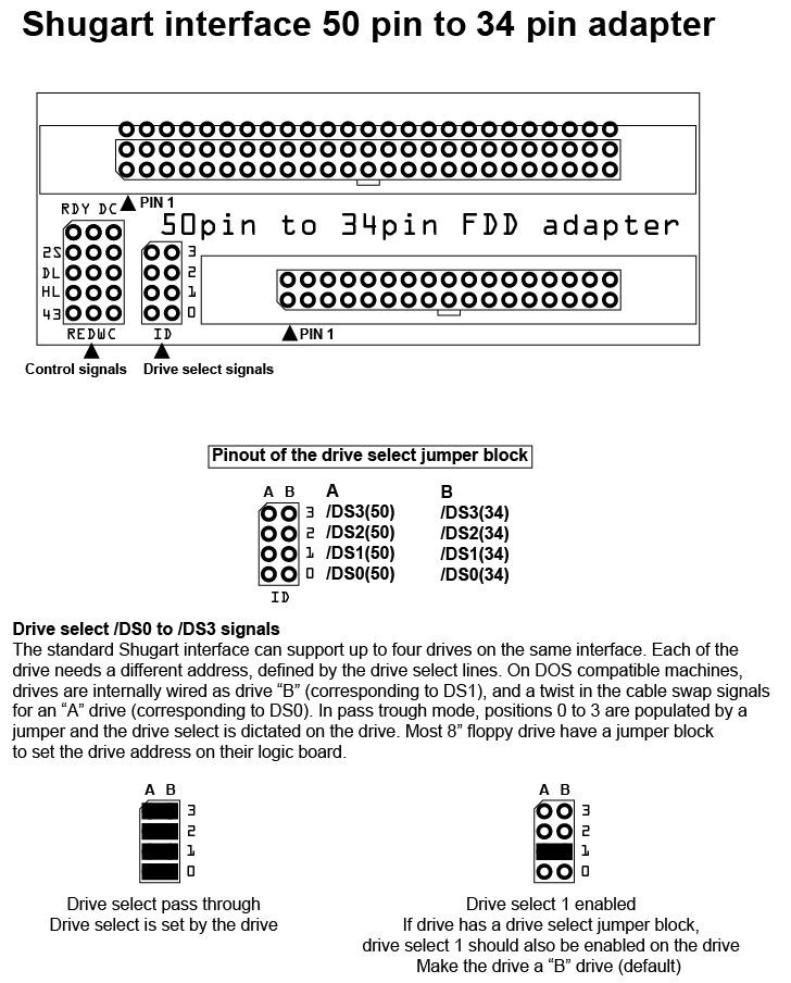
FD Cable is connected after the twist to a shugart 50to34pin adapter - bought on ebay from a french guy (from the same seller this youtuber "Adrian Digital Basement" bought it as well
)
Power Supply: +5/-5V I created out of an pico ATX PSU unit
+24V I get from an external power supply

IMG_3658.JPG

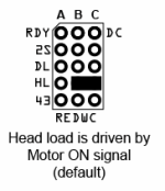
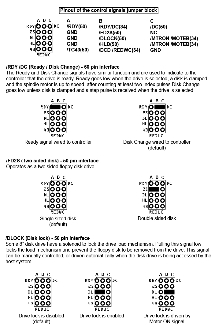
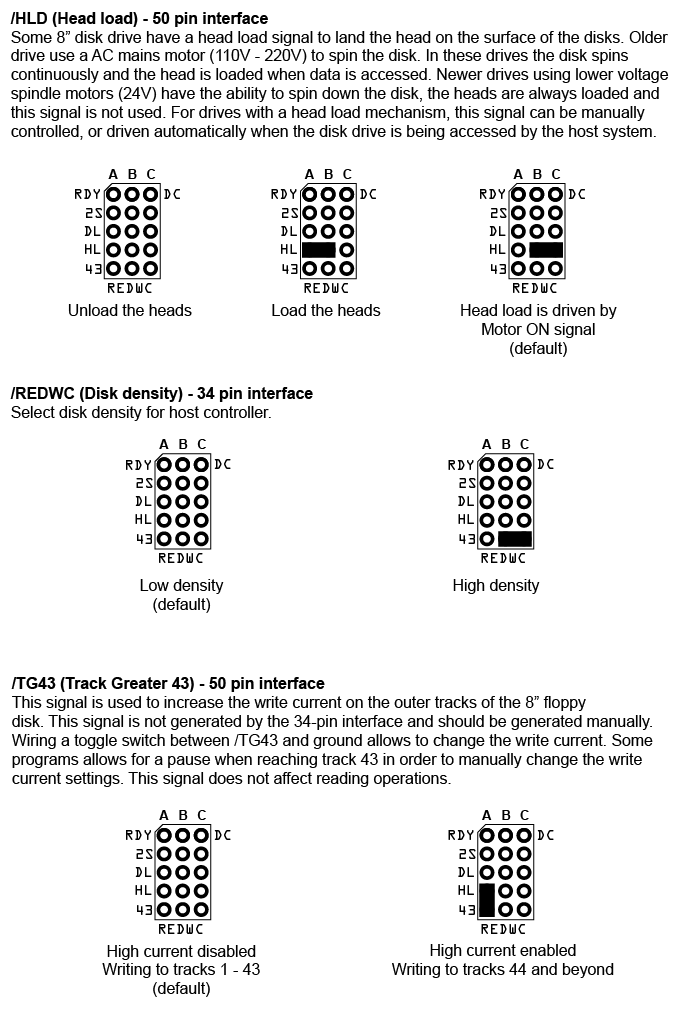
The 50to34 pin connector is set to defaul jumper settings ( see picture)
IMG_3659.JPGIMG_3792.JPG
The FD Cable is working well because I tested it before with a standard 3,5inch drive.

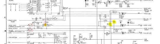
I checked mostly all PCB line if the have a shorten or an interruption since this PCB from the drive is very very old and unfortunately it was not in the best condition :-(


IMG_3793.JPG
As you see, I set jumper to DS2 and terminated via Jumper all bridges from T1, T2, T3,T4,T5 and T6

According to the this video (
) I set in BIOS the A Drive to 720K 3,5"
After booting into freedos I am not able to change drive from C: to A:.
If doing this, I am receiving such an error - btw the drive makes no sound e.g. no sound for the stepper or the solenoid etc. External PSU for 24V is more or less in IDLE (==> 0 Amps! - no current flow :-( )
IMG_3794.JPG

While playing with ImageDisk 1.19 from Dave Dunfield, nothing is working either :-(
I did not changed any default setting and tried the RPM Test ( T ) - but while doing this nothing is happening, no sound, no movement, no LED etc...
in all cases I had an 8" DISK inserted and the door was closed from the drive.

Then I was changing the BIOS settings to 1,2MB 5,25" according to this recommendation (https://retrocmp.de/fdd/8inch/general.htm#intro) but also without success.

Could somebody tell me which steps I should follow to find the root cause of my problem why the drive is not reacting.

BR
Dieter
 
I created my own custom cable / adapter when I did something similar (hooking up 8" shugart to PC) ... with that adapter you could try the settings Adrian used though (see image below.)

Also did Adrian use a cable with or without a twist? I can't recall.

baQIKt3MqpUkmR2nPuHwQdExHGowlZYg_X7XWzRL2S9-rKaF5mgk3NAQ0rkp0gPZe5oRFLZ9GofvP1gI1GAn_Po2qYJA0ba1GEHNluURK983l3iGuPRWAodvWsXrNIqQb_-u3ObX0eVQiiH27UcpRno
 
I changed the jumpers on the adapter to Adrians settings and also connected the drive before the twist like Adrian did.
Nothing is working... :-(

Same when I connect it after the twist.

In Bios I tried 720K at 3,5" and 1,2M at 5.25"

Maybe I should try to debug the drive without computer?
Is there a way to find basic functionality by stimulating signal level on the FD 34to50 Adapter?
  • e.g. activate the Solenoid the lower / upper the Head?
  • turn LED Light on because this light never flashes even when disk is inserted and door is closed
  • check index detector if working
  • etc

in the service manual they mention the "exerciser"
1696615521211.png

Whould that be a possibility to debug the drive on pure hardware level without PC connection?
Maybe some logic ICs are broken - who knows?

BR
Dieter
 
I've got the same adapter (with 50 pin IDC connector instead of edge connector) that I've used with a PC. I use a straight through cable (both on the 50 pin and 34 pin connectors) with the drive pinned as DS1, and 0 on the 50<->34 adapter. BIOS set for 1.2M 5.25" A: drive. Haven't tried a Shugart drive yet, just half height Tandon and NEC 8" drives.
 
I would try to use the drive with Dave Dunfield's ImageDisk Test tools (RPM/Alignment Test). The application ignores the BIOS settings entirely. From there you can at least test the RPM and that the drive is stepping.
 
I am using exactly this tool from Dave but with different settings like one time A and then B:, nothing is going to work on RPM test etc…

Tomorrow I will re test it also with the settings which Eswan recommended 2 post above.
 
About debugging without a computer, this is how I do it. A few dupont wires across the signal & ground. Great for testing head load, motor on, etc. Easy as all the odd pins are ground:

1696621984490.png
 
About debugging without a computer, this is how I do it. A few dupont wires across the signal & ground. Great for testing head load, motor on, etc. Easy as all the odd pins are ground:

View attachment 1265514
Cool - is there somewhere a simple schematic available ? Otherwise I will read out the connections from the pic
 
Cool - is there somewhere a simple schematic available ? Otherwise I will read out the connections from the pic
To address VeryVon's concern regarding the pinout of the Shugart 800-2... it is exactly as described in the SA800 manual. The SA800 came in two versions - the uncommon 800-1 with a built in data separator, and the far more common 800-2 without a built in data separator.

With Shugart 800 there is only one function that can tested "by hand", which is to see whether the drive can be selected and the head load solenoid can be activated. Using the 34-to-50 pin adapter with its default jumper settings and DS2 jumpered on the drive, ground both pins 12 and 16 at the 34 pin connector on the adapter board. The LED on the front of the drive should also come on.

What cannot be tested by hand:
- whether the drive is producing index pulses when a disk is inserted. You need an oscilloscope for that.
- whether the head can be stepped. ImageDisk can test that.
The Shugart SA800 spindle motor is driven by an "always on" AC spindle motor, and the "motor on" signal on the drive cable has no effect on that.
 
With Shugart 800 there is only one function that can tested "by hand", which is to see whether the drive can be selected and the head load solenoid can be activated. Using the 34-to-50 pin adapter with its default jumper settings and DS2 jumpered on the drive, ground both pins 12 and 16 at the 34 pin connector on the adapter board. The LED on the front of the drive should also come on.

I thought this is a good smoketest to see in a quick way how my drive reacts.

I set my 50to34 pin adapter to its default jumper settings, set the jumper on DS2 on the drive itself and power it on with +5 and -5V ( so no 24 because dont need the stepper drive... )

IMG_3909.JPGIMG_3908.JPGIMG_3911.JPGIMG_3910.JPG
But neither the LED or the solenoid come on
 
also with 24V no reaction on the solenoid and LED :-(
 
Good news I am making progress :)
I debugged with schematic the electrical lines from the 34To50 adapter towards to solenoid and relay for turning on the led

I figured out, that the PCB was really messy and a lot of jumper pins were broken.
I desoldered them and added new pin headers into it.

1696766252070.png

I fixed the jumperpins for C, D and X.
Added jumpers on C and D and also B.
For getting the led working I added a jumper on Y

Need your help regarding this question:
Is a jumper on X needed?
And should I keep the jumper set on Y and how about Z?
 

Attachments

  • 1696766244983.png
    1696766244983.png
    251.6 KB · Views: 1
As you can see from the schematic those jumpers "chain together" certain signals to adjust he behavior of the board (that's the way I think of it anyway haha.) See excerpt from the manual below.

1696766900055.png
 

Attachments

  • 1696766897987.png
    1696766897987.png
    297.8 KB · Views: 1
  • 1696767910281.png
    1696767910281.png
    8 KB · Views: 4
Last edited:
I believe the key to getting the adapter settings correct is:

#1 - Map motor enable (A or B depending) to HEAD LOAD (pin 18 on the 50 pin side)
#2 - Then map the corresponding disk select signal on each end:
DS0 -> Drive Select A, or DS1 -> Drive Select B (non-twist cable connector)
DS1 -> Drive Select A, or DS0 -> Drive Select B (twist cable connector)
 
Last edited:
Now my drive is also recognized during booting from bios - I can see it bios menu and also it makes a "noise" when boot procedure is progressed.

With ImageDisk Tool I can execute the Test RPM and Clean Head procedure.

Clean Head is moving the spindle very well and lower and upper the head :)
see video ( the AC drive was off because of noise... )


When going into TEST RPM mode I see that I don’t get a valid signal - also I don’t see any signal when I connect my oscilloscope (probe) on testpoint 12 and ground the oscilloscope on same ground level as my ATX PSU (those ground for +5 and -5V è not the 24V ground…. )
I am receiving always 5V even if I turn the wheel of the disk.

1696779098184.png


Maybe the reason is the open connection (see yellow) – I can not find it on the PCB – could somebody finger point on it for me.

I believe the key to getting the adapter settings correct is:

#1 - Map motor enable (A or B depending) to HEAD LOAD (pin 18 on the 50 pin side)
#2 - Then map the corresponding disk select signal on each end:
DS0 -> Drive Select A, or DS1 -> Drive Select B (non-twist cable connector)
DS1 -> Drive Select A, or DS0 -> Drive Select B (twist cable connector)
since my bios is detecting the drive, and under DOS when I enter A: the system tries to load the disk I am not sure if this settings are still needed?
As you know, I use twisted cable and I connect the 34To50 adapter after the twist. On the adapter I have the jumper settings DS1 active and on the drive DS2.
 
sorry I found the missing connector 13 already:

I am receiving always 5V even if I turn the wheel of the disk ==> TP12


1696787246253.png


Further a connection on the pcb is established betweetn TP12 and TP10.
Unfortunately in the schematic the connection from the 4D logical output Nr 8 is routed to 3C but the input numbers are missing here :-(
It should be one of these 3 pins (4 / 5 / 6) all other are connection and documented in the schematic.

according to Datasheet of 7438 6 should be the output of the NAND 4 and 5 the inputs.
This looks also good.
So basically the electrical connection from the IndexSector Signal should be able to be transfered to PIN 20 of the shugart interface ( INDEX)

What else could be a reason that I dont get a signal displayed (nor RPMs meassured in ImageDisk) on oscilloscpe?
 
Last edited:
What else could be a reason that I dont get a signal displayed (nor RPMs meassured in ImageDisk) on oscilloscpe?
IMD reads from the disk in order to determine rpm. No rpm usually means it can't read. You will have to check test points as documented in 4.6.4 Read and Write Operations. Not to get ahead of ourselves, but sometimes the read amplifier chip will fail. You should identify what IC that is and ensure it's properly grounded & powered etc.
 
IMD reads from the disk in order to determine rpm. No rpm usually means it can't read. You will have to check test points as documented in 4.6.4 Read and Write Operations. Not to get ahead of ourselves, but sometimes the read amplifier chip will fail. You should identify what IC that is and ensure it's properly grounded & powered etc.

With a disk in the drive and the spindle motor running, you should be seeing a pulse of 1.2 msec to 2.2 msec duration at TP12 with each revolution of the disk. If you see no pulse then there is a problem with one or more of the following:
- the index sensor LED
- the index sensor phototransistor
- IC number 1G
 
Back
Top