Coder
Experienced Member
- Joined
- Apr 17, 2023
- Messages
- 80
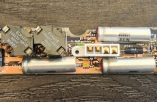
I got this the other day and it won't turn on. I think it may be the caps on the DC/DC power board as I've read they are a common problem, as is usually the case in our hobby. I have replacements in my shopping cart on Mouser, but I wanted to verify the problem before ordering. I started poking around the board and to my surprise, I see the power rails I would expect to see. I have +12v, +5v, and -12v (roughly). But I'm not sure if they are all getting to the proper pins on J1. I was hoping that someone could verify some things for me on a known-good board, or could at least double check my logic. I also saw something I didn't expect and was hoping someone with more knowledge could tell me if it looks ok or if it might be a problem.

I used the ( + ) side of the capacitors for my readings. I know this doesn't test the capacitors, but I also figured they were likely to be on the main power rails. At least the big ones. The values seemed ok to me, but my knowledge is limited. Here's the readings:
C500+4.90v
C510+18.37v
C511+18.89v
These values weren't under load, though. So I'm not sure if that voltage is stable.

The two smaller caps above J1 had the following values on their ( + ) leads.
C504-12.90v
C503nothing (later confirmed it's shorted to ground)
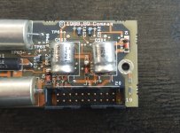
Which brings us to Question #1: I noticed that the ( + ) and the ( - ) of C503 are connected to the same trace with a diode (CR503 between the two capacitors). Checking the ( - ) lead of C503, I get -12.90v as it comes directly from the ( + ) lead of C504. My question is this: Does it make sense for C503 to have it's positive lead connected to ground or does this indicate a possible fault?
I also made the following observations about the pins on J1. Pin 1 is lower left corner and pin 20 is upper right.
PinValue
-------------------
1GND (possibly connected to ( + ) of C503)
2GND
3GND
4GND
5GND
6+12v
7Battery Sense? I forgot I had the power brick plugged in (power switch was off) when I was checking for grounds. When I touched this pin in diode mode with the other lead on ground, the power brick's red light lit up. I assume this light is to indicate the battery is charging.
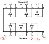
8+5v? I swear I got +5v on this pin during my first pass. But all subsequent passes read 0v. Not ground. Zero volts. Following the trace for this pin, it appears to terminate somewhere beneath a CD4049UBCM "Hex inverting buffer". The spec sheet lays out several usages beyond just as a hex buffer though.
9?
10? This pin also appears to terminate under the same CD4049UBCM hex inverting buffer as pin 8. Both are on output pins.
11GND
12-12v
13GND
14-1v? Not sure what this would be.
15+18v
16+18v
17+5v
18+18v
19+5v
20+5v
If you have a good power board for one of these and some free time, could you check what you get on yours? Especially pins 8 and 10. If I'm reading the schematic for the inverting buffer correctly, I may have a bad chip. The input on the inverting buffer for pin 10 is at just under 15v. I was expecting to see -15v, but it's not reading anything. Is my understanding of how these inverting buffers work correct?
Thanks for any help you guys can give. I appreciate it.

I used the ( + ) side of the capacitors for my readings. I know this doesn't test the capacitors, but I also figured they were likely to be on the main power rails. At least the big ones. The values seemed ok to me, but my knowledge is limited. Here's the readings:
C500+4.90v
C510+18.37v
C511+18.89v
These values weren't under load, though. So I'm not sure if that voltage is stable.

The two smaller caps above J1 had the following values on their ( + ) leads.
C504-12.90v
C503nothing (later confirmed it's shorted to ground)
Which brings us to Question #1: I noticed that the ( + ) and the ( - ) of C503 are connected to the same trace with a diode (CR503 between the two capacitors). Checking the ( - ) lead of C503, I get -12.90v as it comes directly from the ( + ) lead of C504. My question is this: Does it make sense for C503 to have it's positive lead connected to ground or does this indicate a possible fault?
I also made the following observations about the pins on J1. Pin 1 is lower left corner and pin 20 is upper right.
PinValue
-------------------
1GND (possibly connected to ( + ) of C503)
2GND
3GND
4GND
5GND
6+12v
7Battery Sense? I forgot I had the power brick plugged in (power switch was off) when I was checking for grounds. When I touched this pin in diode mode with the other lead on ground, the power brick's red light lit up. I assume this light is to indicate the battery is charging.
8+5v? I swear I got +5v on this pin during my first pass. But all subsequent passes read 0v. Not ground. Zero volts. Following the trace for this pin, it appears to terminate somewhere beneath a CD4049UBCM "Hex inverting buffer". The spec sheet lays out several usages beyond just as a hex buffer though.
9?
10? This pin also appears to terminate under the same CD4049UBCM hex inverting buffer as pin 8. Both are on output pins.
11GND
12-12v
13GND
14-1v? Not sure what this would be.
15+18v
16+18v
17+5v
18+18v
19+5v
20+5v
If you have a good power board for one of these and some free time, could you check what you get on yours? Especially pins 8 and 10. If I'm reading the schematic for the inverting buffer correctly, I may have a bad chip. The input on the inverting buffer for pin 10 is at just under 15v. I was expecting to see -15v, but it's not reading anything. Is my understanding of how these inverting buffers work correct?
Thanks for any help you guys can give. I appreciate it.


