• Please review our updated Terms and Rules here

Need Help with BMC monochrome CRT

Mochatea396

Experienced Member
Joined
Feb 9, 2021
Messages
106
Location
Hudson Valley, New York, USA
I came into possession of a really nice BMC monochrome monitor model BM-1200SU (circa 1981) that has some issues. I've looked extensively for any documentation on this monitor and not a mention of this model anywhere. The issue is the video has a constant vertical scroll that the VHOLD won't correct. I've replaced all the electrolytic caps, removed and tested all transistors as well as testing the coils at the yoke. I've run out of direction and hopefully someone can point me. I posted a link to a small video of it's behavior.

 
With no information on this monitor, a possibility is that the monitor may not be getting suitable sync signals.
Are you thinking that the video signal is the culprit? Thatcan easily be proven by connecting up another working monitor.
 
Are you thinking that the video signal is the culprit? Thatcan easily be proven by connecting up another working monitor.
At this time, I am not suggesting a faulty video/sync source.
What I am suggesting is that the video/sync source being used may not be compatible with the monitor.

(For example, due to a lack of documentation, one must not assume that the subject monitor is compatible with the IBM MDA standard.)
 
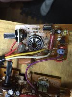
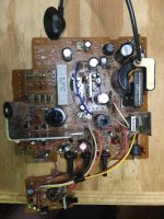
Here's a pic if the main board and the neck board. As I said in my original post, I have replaced the electrolytic capacitors on both the main board as well as the one on the neck board. ALL transistors were removed and tested including the two on the neck board and all tested good.. The only damaged trace I could find only sent power to the red power light which has been successfully repaired. I saw no other issues. I'm currently trying to connect this monitor to an Apple ii.IMG_2665.JPGIMG_2666.jpg
 
Last edited:
Possibly faulty Vhold Pot? Ill be honest I am weary about people claiming bad fly back. I was under the impression alot of faulty flybacks have no video but there is HV. Hopefully some other can chime in with maybe some tests to run. The fact that you have some video means you are 85% there.

Having checked all the Transistor logic is a plus.
 
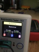
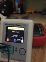
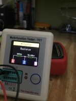
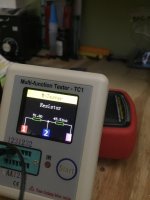
I looked at the Vhold pot and the contrast and brightness pots as well. They have the values printed on them and they are all different, so borrowing from Peter is out. The contrast is 1K, brightness is 100K and Vhold is 50K. I tested them in circuit with a multimeter and the contrast and brightness readings made sense. The Vhold didn't. I removed it from the board and tested it again and I was still getting readings inconsistent with the other two. I cleaned them all with Deoxit once but I did the Vhold again. Quite liberally this time. Now i get readings that make sense. I tested it in a component tester as well, taking readings and different dial settings. See attached photos of my readings. Perhaps it was just really dirty. Unless anyone has any other tests they feel I should be doing, I'm going to solder the Vhold back on and re-assemble and see if there's any improvement.
IMG_2674.jpgIMG_2675.jpgIMG_2676.jpgIMG_2677.jpg
 
It looks like 60Hz interference is getting into the video signal, or horizontal sync circuit. Anytime you see a problem that slowly scrolls through the image, it has to be power line interference. It's hard to be specific without seeing a schematic, but there aren't many places that can be coming from. It could be poor filtering in the low voltage power supply. It could be poor, or no ground on the video input signal.

I would look closely at the B+ regulator circuit. If it's not functioning, then there will be a lot of ripple on the B+ supply. Does the B+ adjustment have any effect?
 
Thanks for your reply Andy. I haven’t touched the B+. The rheostat says 502 on it so that’s 5K. I have some different style 502s here that all test 4.8, 4.9. When I test the one on the board in circuit it starts at .25 and slowly keeps rising. It will clearly have to be removed to be tested accurately. But your right, without a schematic, kind of going at it blind.
I followed the video ground trace and I didn’t see anything unusual there.
 
I'm not saying the adjustment pot is bad; they rarely fail. If the B+ doesn't change when you adjust it, then there is something wrong with the regulator circuit. It's an easy thing to check which might provide some clues. You should also check the B+, and other DC voltages for ripple. An oscilloscope is ideal for this, but most multimeters when set to AC volts will ignore the DC voltage, and give you a reading of the ripple voltage.

With no video signal, if you turn the brightness up until you can see a raster, does it show any signs of brightness variations?
 
Thanks Andy for more suggestions. I appreciate your interest. I didn’t have time to mess with it today but I have to resolder the Vhold pot back on and re-assemble everything, and first thing I’ll do is turn the brightness up until I see raster and I’ll let you know if there are variations in brightness.
I don’t have a scope (one day hopefully) so I’m limited to a craftsman multimeter and a component tester for now. I’ll do the brightness test and we’ll go from there .
Thanks again
 
Its a power supply issue.

The video shows that there is likely line rate ripple on the VDU's DC power supply. This scrolls through the image & raster producing this effect. If the ripple voltage on the input to the regulator circuit drops too low, it breaks through the regulator output onto the sets DC power rails.

It looks like there is likely something awry with one of the 4 rectifiers in the bridge circuit where the power transformer secondary feeds it, or the main large filter capacitor that the diodes are connected to going high ESR or low uF value.

It would be easy to inspect the DC supply with a scope for ripple.

Likely the white ceramic 22 Ohm 15W power resistor there is a bypass resistor to take some load off the regulator. Check that it has not gone open circuit. Check the diodes on the meter
 
Im not sure if the 4 diodes around D70 make up the bridge rectifier; but I was curious what was going on with that one diode off on a diagonal, one side looks disconnected or not where its supposed to be connected.
 
Even I noticed that that one diode looks odd on the diagonal. And there is a hole available for it. And the diode image on the board shows straight up and down. And I know very little about repairing electronics. :)
 
So where is the B+ adjustment? Is it the pot on the neckboard? I cant see the silkscreen.

Edit.. Ok I see it, its near the Glass fuse
 
That diode at 702 was just bent really sloppy. I haven’t had much time to do much with it this week but I did remove the 4 diodes at the bridge and test with a meter and they all appeared fine. Straightened that bent one and put them back on. The print on them was really faint and not much to read but one I was able to just barely see D703 which was GP15G. D701 I could slightly see 5G. Could all 4 be the same? I want to remove the large 15W resistor and test as Hugo suggested and put it back together. I’ll perform those tests Andy once it’s powered up. I’ve just been busy and didn’t want anyone thinking I disappeared on it.
 
Last edited:
Back
Top