• Please review our updated Terms and Rules here

Need help with Osborne executive

No, I believe I sent a video out earlier, the best we have gotten is the display recognizing that something is trying to display, and a small shift from black to slightly lighter black (very possibly just hopeful hallucinations)

Any suggestions on test circuits for the CPU?
I don't have many components on hand, but I do have Arduino uno's, 555 timers, and other assorted components
currently building this one: https://www.makerhacks.com/homebrew-z80-on-breadboard/
 
If you can't get a decent picture (e.g. a boot screen) on the external monitor - you don't know whether it is the logic board that is at fault or the interface between the logic board and the external monitor is to blame...

There are only so many faults you can fix without an oscilloscope I am afraid.

You could rig up something, but this is detracting from a very useful piece of equipment.

If you are really, really stuck, you could look at these cheap things: DSO150, DSO152 (if they can be purchased where you live)...

Dave
 
Okay, makes sense I guess,
While I search for an oscilloscope, what would be the first steps to diagnosing logic issues that would result in improper horizontal and/or vertical sync readings,
The thought process being until I can find an oscilloscope there is no harm in testing logic stuff, if it's working its working, if it's not, we have our (or one of our) issues

Apologies, just saw the edit to your latest message after posting this.
Yes, I have seen some things like this, or those automotive ones that connect to your computer, that will probably end up being what I go for if I am truly unable to find a used/vintage old one

One advantage to testing logic right now is voltage, I can rig up an Arduino as a jerry-rig (and very much not final) way to get somewhat usable readings as an oscilloscope. I don't believe I can use this solution for the vertical/horizontal signals as arduino's have a max input voltage of ~5v (5.5v Technically I believe). Is the peak voltage going through the vert/horiz leads not +12v
 
Last edited:
The problem is (and this is usually the case with a Commodore PET for instance) that the logic is partly working - so you get something, just not what the monitor is expecting...

The video timing is generated by the logic on page 7 of https://archive.org/details/bitsavers_osborneexe_3911242/page/n6/mode/1up (assuming I have got the correct schematic for your machine).

The inputs to the logic are the CHAR CLK* and 60*/50 signals on the left and the outputs are the V... and H... signals on the right.

Dave
 
apologies for the lack of knowledge, but, what are we looking for here?
as far as I am to understand, crt's function differently than lcd (or other more modern display technology) in that they "draw" an image pixel by pixel moving left to right as signals are received through the inputs.
so the signals we are looking for are those currents directing the flow of electrons from the electron beam to the screen in order to illuminate each pixel correct?
what should this signal look like?
how does this work for pixels that are not lit?
this setup makes enough sense for a monochrome crt, but how do multicolor crt's work?
how does one rca cable carry video despite only having a voltage (analog to my understanding) and gnd pin, this makes enough sense to me for monochrome displays, but how does this work for multicolor video?

my home cooked guess is that the crt would be shifting between pixels at a constant rate, and the rca cable would merely dictate if the electron beam should be fired or not,
if this is the case, for color crts is there multiple tubes? and is each one awaiting a specific voltage through the rca?
and, continuing to assume this theory is correct, do all rca devices need to be outputting within what I would imagine to be is a very small tolerance for speed?
last question (apologies) is there any delay issues that could theoretically arise due to the distance necessary for the electron beam to travel to the screen?

apologies for all the questions,
but I believe its better to know how a solution works fully than to just fix it (if that makes sense)
hoping to go into either computer engineering or embedded circuitry design after highschool,
sadly I will not be able to work on ozzy until Monday, but will try to check a local market on Saturday for an osciloscope, there are often stalls selling misc old electronics with vendors who have no idea what they are selling

Thank you,
Kpug
 
The questions you are asking are somewhat complex and can be answered with a bit of googling, or book reading.

For example, the RCA composite video signal encodes luminance (brightness), chrominance (colour), video blanking, and horizontal and vertical synchronisation pulses all into one analogue signal.

However, this comes in multiple flavours depending upon where you live. There is NTSC, PAL, SECAM etc. All slightly different from each other.

All video signal interfaces are the same, irrespective of whether it is an LCD, CRT etc. The differences are all internal to the monitor.

The basic signals are the horizontal and vertical blanking and the horizontal and vertical synchronisation signals. The blanking signals start just before the associated synchronisation signals and finish just after. All the blanking signals do is ensure that the video signal is blanked when it should not be displayed.

Just after the horizontal synchronisation signal is a colour burst - present if the signal is in colour and absent if monochrome.

The luminance (brightness) is then encoded as an analogue voltage level - from black/blank to white.

A colour (chrominance) signal is encoded on top of the luminance signal. This is not a simple process, so I will leave that for your homework and the internet!

The schematic I pointed you to generates the horizontal and vertical blanking and synchronisation signals from a constant clock signal. All of the logic is TTL and gets converted into the RCA composite video signal later.

If the TTL logic is not functioning correctly, you can't expect a monitor to work correctly if connected.

Dave
 
if ttl signals top out at +5v, would it be possible to check the crt by hooking up the +12v supply to a bench, and the ttl signal in to an arduino generating a desired ouput?
if so, would that help narrow down the overall issue?
 
Update:
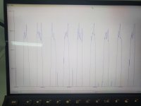
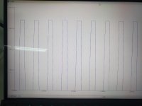
Here are the readings from the horizontal and vertical sync pins on the internal video header. I know it's not great, but I thoguht It might be something to go off of

Vertical sync doesn't seem to be doing anything in particular, but horizontal is spiking, does either look particularly close to correct?

I briefly noticed a white line appear very quickly on the external display after the machine sat on for a few minutes, I was not able to get it on camera unfortunately.
 

Attachments

  • Horizontal sync .jpg
    Horizontal sync .jpg
    5.8 MB · Views: 9
  • Vertical sync.jpg
    Vertical sync.jpg
    6.7 MB · Views: 9
What are the timescales of these signals ? On your picture they seem the same.

One should be at a much lower frequency that the other (ie much longer time between the peaks of the wave)
 
I suspect that the vertical synch signal is 'real' but the horizontal synch signal is suffering from sampling issues (i.e. what we are seeing is not really there).

Dave
 
The Arduino I was using was reporting through a serial connection at 115200 baud, is that too slow?

I can also rerecord tomorrow if you would like to see time signatures
 
Update:
Unfortunately, due to the nature of this project being a personal project at school, I will be unable to work on ozzy for a while as it must remain at school over the summer.
That being said I will keep looking for an oscilloscope over the summer, and will be back working on it right after.
I hope yall will be around to pick up where we left off then, just thought I should explain why there will be a lack of messages for a lil bit.

Thanks for all yalls help so far!
kpug
 
Just to mention for when you get back to it - I had a screen momentarily on my Executive that looked just like your pictures... After I removed and checked the shunt. I removed it, cleaned briefly, and reinserted it, and it all worked well again. Keep in mind that the shunts get old, and could be a common source of problem being introduced to the monitor, so make sure all the shunt connections are carried through correctly.
 
HELLO ALL!!!

UPDATE: oscilloscope acquired!!!!

I have just returned home with a hitatchi v-212!!!! I need to order new probes as the one I am using is VERY janky, but that is not an issue.
will test on ozzy and send results,
question: how does one test the signals needed to be tested?

thanks
 
HELLO ALL!!!

UPDATE: oscilloscope acquired!!!!

I have just returned home with a hitatchi v-212!!!! I need to order new probes as the one I am using is VERY janky, but that is not an issue.
will test on ozzy and send results,
question: how does one test the signals needed to be tested?

thanks

There should probably be a few good articles on stickies on how to repair old computers and use test equipment.

Anyway, your first test is to make sure all the signals are present and accounted for, and they look correct -ie, you have vertical and horizontal signals, and video data signals, and they look correct heading out to the monitor.

You should also have working brightness and contrast signals from the pots and 12v and ground ( though nothing would work if either 12v or ground was missing ).

To test, get familiar with how the oscilloscope works - be careful not to short pins when using it. Especially when there's 12v around. 12v to a data pin will kill it real quick.

You will need to understand the sweep time ( horizontal divisions ) and the voltage per division. Also, reading up a little on what video signals look like will help.

There's a thead here with related video issues ( on a Kaypro, but a lot of the basics are the same ) https://forum.vcfed.org/index.php?threads/kaypro-ii-crt-problem.1248945/

I have an Osborne Exec out at the moment, so if you need reference signals to compare against, check against, let me know.

Once you've confirmed you have sync and video, and the contrast/brightness work, then you move onto testing the monitor.
 
Back
Top