• Please review our updated Terms and Rules here

Need help with Osborne executive

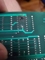
This may be far fetched, and probably wrong, but I'm not sure that mark is from something on the board. The center of the the mark is not in line with the pins for the cap, and there is a small pattern to the burns. Is it possible something inside the case arced spectacularly to this board?

Edit: I was also wondering if the popping of the old rifa caps may have caused it as if I remember correctly, the psu sits below the ram board in the case
 
Is the capacitor still intact?

If it is, it is unlikely to be that (especially if you can read the value)!

A burn mark like that from a capacitor would be unusual (as I said) unless it had 'exploded'. The usual culprits (in this case) would be tantalum bead capacitors - but the construction is unlikely to be this for the stated value.

If you remember, I did ask for some photographs... A picture paints a thousand words and all that...

You could be correct in that the burn mark occurred as a result of some nearby component elsewhere.

EDIT: I did find the bulk decoupling capacitors on the schematic:

1715247263144.png

C1 and C2 appear to be described as 10 nF.

I also had another look at the photograph of the burnt patch. Is it possible that the one lead that is surrounded by the burnt patch has shorted out against something?

1715247492089.png

It looks to me as though that lead of the capacitor is connected to the +5V rail (judging by the pinout of the interconnected ICs) - so I was just wondering whether this bent-over lead has accidentally shorted out to (say) the 0V rail?

The lead appears to be at the epicentre of the destruction...

Dave
 
Last edited:
Apologies, you are correct as to the position of the pin in relation to the spot.

Attached is a photo of the capacitor, I cleaned up the burn patch slightly as well:
 

Attachments

  • 20240509_064906.jpg
    20240509_064906.jpg
    1.9 MB · Views: 9
  • 20240509_064854.jpg
    20240509_064854.jpg
    1.8 MB · Views: 9
That is not a ceramic capacitor but a glass bomb!

Is the capacitor damaged? It looks like a small piece of glass has broke off.

Something has happened there hasn't it?

Dave
 
Yes, it does appear a small chip developed on the side of the cap.

What do you mean by glass bomb?
Should I just replace the cap? If it still reads the correct capacitance is it still okay?
 
I would bet that pin has touched ground and burnt the track rather than a fault with the capacitor. Especially as the topside shows no real heat damage.
 
>>> What do you mean by glass bomb?

When these things go faulty (when powered) they quite literally (most of the time) explode with a large bang...

>>> Yes, it does appear a small chip developed on the side of the cap.

If it isn't faulty now, it will be shortly (with the glass chipped)! I would replace it to be sure.

>>> Am I cooked?

Just make sure the PCB track is still intact... If not, let us know. If the PCB track has vaporised, then the capacitor will not be doing anything - and it will not be connected to the PCB track on the component side - so there may be some of the logic circuitry that is not being correctly powered.

Dave
 
How would I go about ensuring the track is still intact?
Also, can I replace it with an electrolytic cap?
If the track is not still intact is there a way to fix that?
 
>>> How would I go about ensuring the track is still intact?

Use your eyes to see if there is any copper left under that black mess...

You can also use a multimeter (configured for low resistance measurement) with the power OFF. Check from the same end of C1 to C2 (i.e. with the pin that is burnt) for a low resistance.

>>> Also, can I replace it with an electrolytic cap?

No. Electrolytic capacitors are a much higher value and perform a different function to this type of capacitor.

>>> If the track is not still intact is there a way to fix that?

Yes, with a stiff piece of wire from the pin of the capacitor to the nearby PCB rail to replace the segment of PCB track that has vaporised.

Dave
 
Ok, as far as I can tell, the track (is a trace and a track the same?) is still intact

Measuring resistance between the top pin of C1 (where the black spot is) and the top pin of C2 we get a resistance of 0.2 ohms.

Next step is to replace C1 right?
 
I have a few of these labelled "104"
I believe them to be ceramic caps.

Would this be a suitable replacement?20240509_134351.jpg
 
>>> (is a trace and a track the same?) Yes.

104 is 100,000 pF = 100 nF.

What is on the schematic is 10 nF. This should be marked as 103 (10,000 pF = 10 nF).

Are you sure the glass capacitors are marked 104?

Anyway, the machine will quite happily run without capacitor C2 - or you can install that brown 104 potato!

Dave
 
ok, so, just to recap (pun intended).

I can replace C1 with the 104 "potato" linked in the above photo and we should be in the money?
 
Yep.

A decoupling capacitor is not at all sensitive to the value - providing it is not silly that is!

Dave
 
sadly I will not be able to test the ram board with the new caps until monday.

However, I am looking into ordering new equipment and parts to have around the shop.
any suggestions on what to pick up?
 
Just to let you know - it is unlikely that replacing the capacitor will make any difference to your fault...

Dave
 
Alright, will work on finding on oscilloscope over the weekend. Seen some ppl make them out of Arduinos, would this suffice?
 
Back
Top