daver2
10k Member
Isn't it "OLD @1:" - the colon being significant (after selecting the desired file to load).
Dave
Dave
1. I would check the smurf grenade (tantalum bead capacitor) C668. This is across the -20V and GND/0V power rails.
2. -20V is also used on the tape drive. Perhaps disconnect the tape drive (J-82)?
It might make sense to just measure the resistance across the -20V and 0V/GND power rails (with the mains supply OFF of course) to see if there is a direct short circuit anywhere. Use a low Ohms scale (say maximum 100 Ohms or 1k).
Dave
Isn't it "OLD @1:" - the colon being significant (after selecting the desired file to load).
") !
!It can be alright. If there is three-state drivers which are not active then the bus can look like this if there is no pull-up resistors. A non-driven TTL-input ends up at around 1.7 V or so. One need to check all the bus drivers if the enable signal is active or not. Haven’t checked the 4051 schematic myself. Is there pull-up resistors on the bus-lines or not?
Reading:    BD 4C
Should be:  BC 4B
            -----
Difference: 01 01One step forwards...
Before you do that however could I suggest using your oscilloscope to check that/those strange data line traces that we had to make sure they have gone away? Cause and effect... Has the original problem we observed gone away or not?
Can you also check the /NMI and /IRQ signals to make sure these look partially sensible (i.e. not stuck LOW as one was).
EDIT1: I am thinking that the 6800 CPU is now working properly. This may be either a faulty keyboard PIA or faulty keyboard circuitry. There are a few TTL chips that are critical to the operation of the keyboard. I’ll give you a couple of points to monitor with your oscilloscope after lunch.
EDIT2: The <PAGE> key is read as a conventional keyboard key. So, if this interface is not working correctly, you won’t be able to ERASE the screen.
. Big brother is watching...The replacement for U337 (SN74LS93N) has arrived and has been installed.
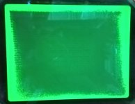
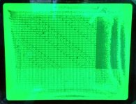
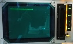
The screen still has the glow around the edges and I can't clear it with PAGE. However the display does now show a flashing cursor in the top left corner and all lights except POWER turn off a second or two after power up AND STAY OFF! Many keys respond with two or three random characters and some do not respond at all. The AUTO NUMBER key actually responded by printing '100 ' on a new line which shows that BASIC is working. However, most of the keyboard is not responding at all or as it should be.
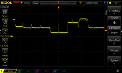
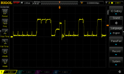
Having checked the signals on we now have:
P14 [A] - 52.068kHz (we have RCCLK coming in from the clock circuitry on page 04_02-02)
P1 - 26.034kHz (output to U431)
P8 [Qc] - 6.5085kHz (output to U435)
P9 [Qb] - 13.017kHz (this is the output to KBCLK-0)
P11 [Qd] - 3.254kHz (output to U217)
P12 [Qa] - 26.034kHz (output to U431)
I must admit I expected to see about 3.25kHz on all three ouputs (Qb to Qd) but instead I am seeing 3.54kHz on Qd only and multiples thereof on Qc and Qd. Maybe I misunderstood that.
In any case, I traced the 13.017kHz square wave from p9 which is the KBCLK-0 signal to the keyboard on U6p9 as well as U1 p18 and p19. KBHALT-1 is LOW so things appear to look good up to this point. However here is where I ran into further problems. The KEY1 signal on U6p3 is HIGH. There seems to be no response to keys being pressed. Checking the outputs on U1 pins 1 to 11 are LOW (no activity), pin 13 is HIGH and pin 14+15 are also LOW. There is activity on pins 18+19 (G1 and G2) as well as 20-23 (A-D). There is activity on U4 pins 1 and 8,9 and 11 but pin 14 is HIGH.
I checked all the keys to make sure none are shorted and didn't find any problems. The only key that read short whas TTY LOCK which was pressed down but releasing it made no difference. I guess this must mean that U1 is faulty as you said the outputs should be oscillating?
Still, a further step forward.