• Please review our updated Terms and Rules here

New, to me DEC PDP8E

Well..... spent the last couple of days, cleaning and removing the corrosion from the front panel control board. Been using alcohol, vinegar, cotton swabs, old toothbrush and small paint brush. The alcohol does a good job on the oil removal and the vinegar helps with the corrosion. Inspection found a couple broken resistors, two frozen switches and a few suspect lamps. I loosened up the switches, but they do not make up. I may try and remove one of them later to see if I can open it up and make a repair.

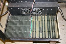
Next I removed, photographed and labeled the cards. One item is that the card space is divided into two areas. The front has a 20 space omnibus with all the DEC cards in place. The back is a different motherboard. It is made by Kearney and Trecker, here in Milwaukee. My Father-in-law worked there before and after the War. This back mother board has 15 KT boards in it and physically connects with two heavy ribbon cables to the M863 12 channel I/O board. One thing that puzzles me is how all this stuff connected to the machine tool. I didn't remove the unit and was not there when it happened. There are a few empty sockets which could have been used to connect to the machine tool, but how did the wiring come out. Usually there are a bunch of terminal strips for external wiring. Something to find out, when I go back to the machine shop and talk to my friend.

I want to remove the two motherboards and clean them. They are oil covered and the omnibus has corrosion on the first two slots. There seems to be a handful of metal chips in the case also. So a good cleaning is needed, Then on to the power supply. Another odd thing is the power supply connection cables are rather hard, very inflexible AND the wire size is small. I saw on one of the power supply prints, the +5 can supply 20 Amperes. The wire looks no larger than a #18 wire. The plugs and sockets are also beat up some. Maybe some of this will be changed out also.

Mike
IMG_0233.jpg
 
I loosened up the switches, but they do not make up. I may try and remove one of them later to see if I can open it up and make a repair.

Next I removed, photographed and labeled the cards. One item is that the card space is divided into two areas. The front has a 20 space omnibus with all the DEC cards in place. The back is a different motherboard. It is made by Kearney and Trecker, here in Milwaukee. My Father-in-law worked there before and after the War. This back mother board has 15 KT boards in it and physically connects with two heavy ribbon cables to the M863 12 channel I/O board. One thing that puzzles me is how all this stuff connected to the machine tool. I didn't remove the unit and was not there when it happened. There are a few empty sockets which could have been used to connect to the machine tool, but how did the wiring come out. Usually there are a bunch of terminal strips for external wiring. Something to find out, when I go back to the machine shop and talk to my friend

Another odd thing is the power supply connection cables are rather hard, very inflexible AND the wire size is small. I saw on one of the power supply prints, the +5 can supply 20 Amperes. The wire looks no larger than a #18 wire. The plugs and sockets are also beat up some. Maybe some of this will be changed out also.

Mike

View attachment 27434

Hi Mike,
I find this two different motherboard system very interesting. Gives me some excellent food for thought for a project with an 8e that I have partial remains of.

If you read Oscars post here on the DEC forum about the PiDP, maybe if you cannot restore/repair the switches you have, and not find any replacements, its just a thought that, the ones he is using for that 8i kit may, at a pinch fit, with some leg reworking.

As to your power supply, the 8e supply I have has Molex sockets on the side of the supply. and the backplane, has a cable from it up to supply that has a mating plug.

Anyways, I am guessing you have contacted your friend at the machine shop, at least by phone, and spoken to him indicating you have questions, lots of them and well asking him not to throw out or dispose of the rest of any bits of the NC or rack (?) this 8 came out of, till at least your have been back.

You comment "Something to find out, when I go back". Time does have a habit of slipping past, and well before you know it 6 months may pass.
And since your friend had finally made the decision to part with the 8 to you, they may have infact made a decision to dispose of the rest of the machine fairly quickly.

I have seen and experienced that quite a few times in my life.

You get one bit, because maybe that all the room in car or that you can carry. You go back the next day or even that evening and the rest is gone.

Just my 2 cents worth, as I can tell your quite focused on the bit you have.
 
I'll see my friend soon enough. We have breakfast at least once a month. The shop that is another matter, but I'll have plenty of opportunity to ask and look.

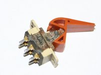
I just got the A0 switch off the front panel control board. Looks pretty bad, but who knows. If it can be fixed I'm sure some other type of switch can be used.

IMG_0240[1].jpg

IMG_0241[1].jpg

While the switch is out, maybe I'll replace the components that are near it.

Mike
 
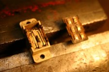
Well.... I gently opened up the switch. A couple of the tabs were rusted to the point where they broke off, but that should not be a problem. The switch was loaded with rust and corrosion.

IMG_0242.jpg

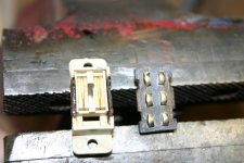
I cleaned the offending stuff out and buffered up the contacts. A little floor wax (very little) was used to lube up the slider and the switch should be OK. Tested it and it works fine. The slider moves easily and should be no problem for the plastic lever. I figure that a little glue will help hold the case together.

IMG_0243.jpg

It's getting late, maybe tomorrow I try the A1 switch.

Mike
 
It's very common for an NC machine, even today, to have two complete computers, interfaced. One for motion control, and one for the high-level stuff. The motion controller probably won't be much use to you.

I don't think I've ever seen or even heard of a K&T NC machine. So much of that history is gone forever. Unfortunately, most of the people who ended up with these machine had absolutely no interest in them.
 
I don't know if my 8e is an NC, but it is like yours with the power supply transformer on the side, not the back.
Bill
I've never heard/seen of a PDP-8/E with the power-supply anywhere but on the side, do you know of any links/descriptions of that configuration? I found a reference to an OEM rack-mount version of the PDP-8/E, was this the one with the PSU at the back perhaps?

http://homepage.cs.uiowa.edu/~jones/pdp8/models/#PDP8E
 
I've never heard/seen of a PDP-8/E with the power-supply anywhere but on the side, do you know of any links/descriptions of that configuration?

Unless Bill was actually thinking about an 8/F or 8/M. I have seen both configurations for the switching supplies used in those.

Kyle
 
Not sure how the idea of the power supply was on the back, it's not. It is on the side. Had a power outage at my home for most of the day today. But finished up the two frozen switches they work very good. Tested all the other switches and they all seem OK. The corrosion on the right side of the front panel board affected about 10 of the lamps. The pins were froze in the pin sockets. Some of the pins were rotted off and the lamps fell off and others were loosened up and removed with a little vinegar. I'm making a list of parts that I'll need for the front panel board. Also pulled the power supply out of the base pan. The pan was full of oil and metal chips. Washed it out and started to sand the rust off the front. Once it's clean, it will be painted. Both mother boards (is that what they are referred to as?) also need to be De-greased and the first two omnibus slots show green corrosion and will have to be cleaned. Inspection shows that the power supply plugs and sockets, (J1 through J6) are all cracked and broken. The wiring to and from these connectors has hard and broken insulation and I should replace it. Making progress.
Mike
 
Hi All;

Mike, speaking of Cars, what is the car in the picture next to Your name ?? The picture is too small for me to tell.. And do You have it or one like it ??

THANK YOU Marty
 
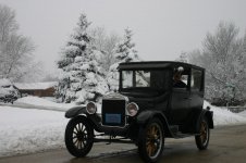
The car in the picture is my Model T. It's a 1926 TuDor. I found it in the north woods maybe a dozen years ago and restored it to nice shape. It's a driver not a show car. My son and I take it for a 1000+ mile tour each August. We have a lot of fun with it. Here's a larger picture.

IMG_2274.jpg

I've been cleaning the omnibus of the corrosion and been thinking about the pinout of it. I have not found any information regarding how the pins are referred to. Where can I look?

Thanks Mike
 
I did a partial restoration on a 1924 TT Rack Body. It eventually ended up at the Shelburne Museum in Vermont. They used it to give kids rides around the museum. Since it maxed out at about 20 MPH it would take a very long time to do a 1000+ mile tour.
 
Mr. Thompson, The Model TT is a truck and the rear axle ratio is very low, hence the max speed of 20/25 MPH. The Ford cars of that era had a higher ratio and were capable of 35/40 MPH. We usually take 7 to 10 days to cover a 1000+ mile trip. I had the car on the Michigan Speed way a few years ago, and got her up to 52 MPH. Never again, it felt like a wash machine full of walnuts. I'll keep her to 35 or less, but still is a lot of fun.

I've been checking the continuity of the omnibus using the front panel board. I found that a number of the pad traces on the front panel board have corroded away. I'll have to repair this.

Thanks Mike
 
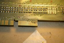
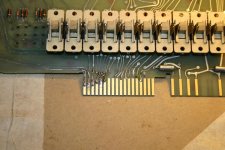
Just finished bridging over a dozen or more pads on the front panel control board. The corrosion had eaten away the the top of the pad, separating it from the CB trace. The pads were green, like copper oxide. After I used a little vinegar remove the oxide the pad turned rust brown. DEC must used brass and not have used gold for pads. Otherwise why would they be affected this way. I tried to keep the solder and wire jumper as high as I could so there would be no problem with the omnibus. The top end of the pads were corroded the worst and I had to keep the solder rather low. I tried to keep the solder as small as possible and then filed it down to a slight taper. The board goes in the bus.

IMG_0252.jpg

IMG_0253.jpg

This board has more corrosion on the board proper. Later I'll make some more continuity checks when I replace some of the affected parts.

Mike
 
Back
Top