• Please review our updated Terms and Rules here

North Star and Compupro CPU-Z

Ttpilot

Experienced Member
Joined
Nov 8, 2020
Messages
100
Location
South Dakota USA
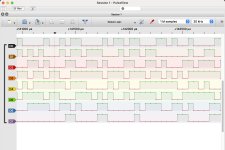
My North Star motherboard seems to be in working order (thanks, everyone). I decided to plug in my Compupro CPU-Z board and try to sort it out. At first it seemed to be working okay, at least I was getting a good clock signal and RESET* seems to work. I installed a couple of 2kx8 EPROMS that consist of NOPs with a jump back to 0000h at the end. I attached a logic analyzer to the address pins of the Z80 and got this
9855EAD6-0393-42DF-B5AD-012F636B1FF7.jpeg

It's obviously not progressing through the addresses or reading the EPROM. The other signals look wacky, too

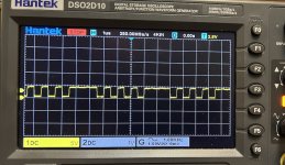
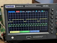
Here's the clock M1* (pin 27) and CLK (pin 6). These don't look right. I've got another Z80 coming in I can try. I'm also working on a breadboard setup to test the Z80s
IMG_4281.jpeg
 
Why do you think the /M1 signal “looks” abnormal out of interest?

I agree that the data bus doesn’t indicate NOP instructions though - but that is a different (and separate issue) to anything to do with /M1.

Another observation, why do you think the EPROM actually begins at location 0? This is where a Z80 starts executing code from. However, most of these systems run CP/M, and thus requires RAM at location 0. There is usually some form of power up / reset ‘magic’ that causes the Z80 to branch off to a different location other than 0 (usually the top of memory somewhere).

What are the settings for switches 2 and 3. These specify the start address base of the ROM and the power-on / reset jump address.

Dave
 
Last edited:
The address of the onboard EPROMs can be set on the board, as can the power on and reset addresses. These are set to 0. I've also tried setting it up at F000, for instance, with no change.

I'm judging the performance of M1 according to what is presented in Fig. 5 of the Z80 CPU User Manual (2016)
 
OK.

What I usually do first off is to store 0x76 (HALT) into the EPROM and see if the CPU halts on a power up (/HALT pin of the CPU - 18 - should go LOW). A very simple test - but it tells me a lot!

I wouldn't put too much faith in the documentation. The Z80 technical manual identifies that M1 should go low for three T cycles (assuming no wait states) - and is triggered on the leading edge of the clock cycle. Note that there is a 0..130 ns potential delay from the clock edge to the transition of the /M1 signal.

Elsewhere, the same document identifies /M1 going low for two T cycles...

This behaviour may also be applicable to a subset of Z80 CPUs - and may be different for second-sourced devices?

If the /M1 signal is incorrect - then the CPU must be faulty. Otherwise, I wouldn't worry too much...

If you are monitoring the lower eight (8) address lines with your logic analyser, then don't forget that the Z80 CPU will be 'polluting' your traces with the automatically-generated refresh cycles.

Dave
 
I have had some success with the Z80 board. I ran it with the HALT EPROM with successful results. Next I tried a little routine I saw on Circuit Breaker's YouTube channel. It consists of 3 NOP instruction followed by a jump back to the start. This results in an easily visible pattern for /M1 on the scope:

IMG_4315.jpeg

It successfully passed this test. The smaller NOPs followed by the JP instruction are clearly visible and match the YouTube example. So I know the board is functioning, reading instructions from the EPROM, and executing them. Next will come debugging it with OUT instructions to see what's going on with the serial port
 
I was going to suggest exactly the same test myself (a few NOPs and a JMP).

And the next test program would be some sort of I/O, followed by some sort of memory write/read.

Have you got a UART that you can output text to somewhere?

Dave
 
Good choice...

I have the source code for a little Z80 debug monitor that I 'stole' from a Cromemco 4FDC. I basically 'butchered' it so that it just worked with the UART on the 4FDC. This allowed you to peek and poke about with memory and input and output with ports - and was the next logical step in getting a Cromemco operational.

I should still have the source code somewhere if you want it.

You will have to butcher it again for your particular hardware environment of course...

Dave
 
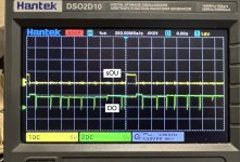
Any help is appreciated. I modified the NOP-JP routine to include an OUT command before the JP. It also shows up on the /M1 trace, and the /IORQ pin goes low during the OUT instruction. The data line pins on the Z80 seemed to be functioning okay. I traced them through the 81LS95 at U42, where they seemed to be functioning okay. This leads to an LS244 at U41. The incoming data lines seemed okay, but I got zip on the outgoing lines, which feed the data pins on the motherboard
 
My mistake. DO0-DO7 are getting on the bus just fine from the CPU-Z. My EEPROM is just sending a steady stream of ASCII 'X' characters to the output port. Those show up synced with the /IORQ and sOUT signals, and it's easy to see the bits of the 'X' character on the traces. I am curious, though, about how raggedy the data out signals look, although they're appropriately high or low with /IORQ and so forth

sOUT and DO4.jpg

Should that DO4 signal be so jittery?

I'll start hunting through the motherboard serial port signals next. Something seems to be getting lost by the time the data lines reach the 8251 UART
 
Some more success! I added a couple of statements to initialize the 8251 before it starts printing 'X's:
Code:
        ORG    0000h
        LD       A,040H   ;reset uart
        OUT    (3),A
        LD       A,04fh   ;04eh = 8-n-1 9600 baud
        OUT    (3),A
        LD       A,027h   ;027h = enable receive and transmit
        OUT    (3),A
        LD       B,'X'       ;print X to terminal forever
Start:    IN   A,(3)       ;query the UART
        AND    001H      ;ready to send?
        JP       Z,Start  ;nope, try again
        LD      A,B      ;okay, send it
        OUT   (2),A
        JP      Start

When I ran it my monitor started printing. They look like they might be lowercase 'x's, though, so I'm going to experiment a bit more. Oddly enough, I don't remember my CP/M BIOS having an initialization routine for the 8251, but then I won't be able to see a copy until I can read the damn floppy disks. For that, I'll need to sort out the Morrow Designs DJ-DMA fdc
 
I have just checked the data sheet for the 8251 and it appears pretty quick to perform a reset. It won't hurt to add a couple of NOPs though.

However, the device contains a hardware RESET signal so (in theory) no software reset is actually required (providing you only run your test program after a hard reset).

I agree with your configuration - although it appears strange to me that the divisor is set for x64. Usually, for a UART, the divisor is normally x16?

The difference between an 'X' and 'x' character is data bit 5 - so it would be sensible to concentrate on this data bit.

It may also be worth modifying your test program to output all characters from 020H [SPACE] to 07EH and then HALT. That will allow you to see if there is a faulty data bit somewhere (not only will the letters turn out incorrect - but various symbols will as well).

May also be worth checking if your 'terminal' device is accidentally converting to lower case (just a thought)...

Dave
 
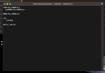
Good call on the x64 setting. Even the schematic says x16. I don’t know where I came up with that. Anyway, it seems to be working pretty well now, once I got the right mode setting for the 8251. I wrote a little app that prints out a title, then loops for input, which is echoed back. I’m not sure why the app spews out some extra characters at the start though

54B55EB4-BAF1-4403-ADF6-870F0F48D36A.jpeg
 
The CPU-Z board and motherboard are functioning correctly at last. I made a modification to the test program to put in a delay loop between setting up the 8251 uart and the rest of the routine. That fixed the problem with stray characters being printed on the screen. Thanks for your help on that, Dave
 
Back
Top