• Please review our updated Terms and Rules here

Notes for IBM 5110 keyboard replacement (pin out measurements)

You might look at the "black pill" (STM32F401 or STM32F411) boards. Yes, I know--hugely overpowered for the job, but isn't everything nowadays?

FWIW, I find it curious that the PyBoard (STM32F405) is cheaper than either of the black pill boards. My favorite in this lineup is the STM32F407 "black" board--comes with SDCard and battery-backed RTC.
 
:) Yea I'm not sure what I'd do with the gyroscope. But with the integrated DAC audio, I suppose I could emulate the sound of the 5110 keystrokes as they are pressed. ;)


My original plan was to use the "modern" PC parallel port (I still have a few old laptops with parallel ports, and USB-DB25 cables exist). This way, you effectively just use a whole PC as the terminal input interface to the 5110, and you have all the normal PC development tools and infrastructure.

Parallel port has 8-data pins, a STROBE pin, and I thought I could hijack one other pin for the Parity-pin (like PIN 16 INIT ?).

An article here is a good refresher about the parallel port, and it discusses some aspects related to open drain.

I'll mull it over some more. Seems like a parallel cable, some 33 cent DIPs, and a deck of resistors might be able to do this from a PC?
 
I'm not sure if this could be plugged in-line with an existing keyboard. i.e. electrically I'm not sure is basically two keyboards could be connected at the same time? i.e. this will probably a unique 1-off build, since I'm not sure folks who have functional keyboards already will make use of something like this.

You're probably in an O(1)-off build situation anyway even if you count the people with functional keyboards. The 5100/5110 community is not huge :)

That said, I have a functional 5100 keyboard, and if a gizmo like this is going to be the way to bridge the modern world into my machine, I'm interested... Like you said earlier, I hope that the real answer is to type in a short bootloader that lets you bit-bang code in and out of the I/O port in back, but if that doesn't materialise, then a keyboard substitute will be a fine alternative.

Happily, if the keyboard data lines really are operated by open collector signalling, then there's very likely no incompatibility with what you're planning to build. It doesn't matter if there are two devices that can pull down the data line at once --- in fact, except for some garbled input, there's nothing too risky electrically-speaking even if you try to type on the keyboard while the phantom typist is also manipulating the data lines. This is only true so long as your gizmo is also using real open-collector signalling too (or using the design precautions for push-pull or "totem pole" outputs that Chuck mentioned earlier).*

(Using unmodified push-pull signalling would be a different story, since the "push" part adds a switchable low-impedance (aggressive!) +5V source to the data line, and if the keyboard tries to pull the data line down while your gizmo is busy pushing it up, that will be much like a short circuit and will have similar regrettable consequences.)

Either way, I look forward to seeing what you make. Now, I admit that I hope that it's not something that uses the parallel port, since I don't have one of those and some jellybean microcontroller/single-board computer will be easier for me to source! But this is of course your project, and I can just learn from what you do and make my own solution if I need to. Good luck!


* This open-collector-specific situation has a name, in fact: "wired-OR" (if link is broken, try Google's cached version). It's called this because you are performing a logical or operation on two open-collector outputs by simply wiring them together.
 
Last edited:
Parts on order, will take some R&D time and also lots of travel coming up. As I do have two 5110's without keyboards, I may try both solutions. The parallel-port approach may be an easier "proof of concept", to verify the timing and flow of operation, and see if any letters show up at all - I could probably breadboard it.
 
Ok, some YT-videos later and now with a variety of small transistors and variety or resistors...

Here is what I wired up, where the LED was on until I "pressed the key" (closed the switch). At which point, then the voltage dropped depending on what R2 I used (but basically under 0.2V) [i.e. pressing the switch turned off the LED, which is what we want]

1654235391686.png


But first let's talk about the R1 (resistor at the top). As discussed elsewhere, the BaseIO (that the keyboard IO is routed through) apparently has some "330 ohm" resistors. I don't know how many are inline, or if those resistors are even involved in this. All I know is that at the end of the green keyboard connector, I read 5v.

For this little mock up, I somewhat randomly picked a transistors and tried a variety of R1 values (as listed above, from 68ohm to 22k ohm). I went with the NPN transistor, and "S9018" is the part number marked on it.

And for starters I kept R1 and R2 the same. Whatever the draw in the BaseIO components (when I go to integrating this into the 5110 system), I just need R2 to be large enough to "push" the voltage down to under 0.2v when the switch is closed. And I guess that's the risk - I don't know what R1 really is (inside the 5110 system), and R2 should be equal to or greater than that value?

I measured the resistors on the keyboard PCB (could go by the color strips, but measuring just in case). In the 3 groups of 10 resistors on that PCB, the highest resistance is about 1.5k ohms (yes, 1500 ohms -- surprised not over 10k ohms, but I measured them twice; I'll double check again tomorrow when I have better lighting). So I think I could just start R2 at 2k ohms and work my way down.


So, how I think this will look "for real" will go something like this (obviously not to scale! ):

1654236996301.png
Eventually repeat this for all of KBD_P and KBD_0 to KBD_7 and KBD_STROBE. (think I'll have to finally face my worst nightmare and do some soldering)

The "easiest key" for the IBM 5110 is "9" -- to type 9 is just "pulling down" two pins: KBD_P and KBD_STROBE. Lots of things could go wrong, but like with my 5110 PSU work, I just happen to have an extra 5110 to (potentially) sacrifice for science (since we're still guessing on the 5110-side of things). I think I'll wire up two of these transistor circuits, and if I can get a "9" to show up -- If so, then it's off to phase 2: control the switch actuations via a parallel port.
 
Last edited:
Thanks for the diagrams! They make this conversation very clear.

I want to talk a bit about the top of "Figure 1", above the dotted line. This part simulates the computer, and while one half of the simulation is accurate (that is, you have a signal line pulled up with a resistor of some value), I think the other half is less accurate, in an important way.

An LED is a component with little resistance --- it provides a low-impedance path to ground. If you want to get it to do its function (i.e. light up), this is a good thing. You need to pump a lot of current through an LED (relatively speaking) to get some light, and low impedance means you can just pour that current right in.

For you, the current is coming from the +5V supply behind R1. Forget for a moment the fact that we've been thinking of R1 as a pull-up on a signal line: R1 is like the handle on the faucet pouring current into the circuit. Smaller resistors open the faucet wider and wider.


Inside the 5110, the keyboard's signal line isn't going into an LED. Instead, it's probably connecting to the base of a transistor inside some IC. This component doesn't need much current to operate at all (that's a transistor's miraculous power of amplification, after all). Odds are that it's wired up in a way that it offers a fairly high-impedance path to ground. This allows the equivalent to the pull-up resistor R1 to be much smaller.

That's a good thing for you, because you can use a much smaller transistor.

Right now you have to sink a lot of current through your transistor in order to turn off the LED --- about 5V/300R = 15mA. The transistor you've selected for the job is pretty heavy-duty; it's a good choice for the "Figure 1" circuit. But there is no component anything like that transistor on the keyboard.

When you get to the point where you're designing the parallel-port controlled circuit, you may want to be able to use more convenient lower-power components like buffer and parity generator ICs. Or, if you change your mind and use an Arduino or some other microcontroller with +5V-tolerant inputs, you'll very likely require no interfacing components whatsoever: you'll just be able to plug the chip right into the signal lines and go. The transistors inside a microcontroller are very small indeed, but that is unlikely to be a problem here: no matter what those resistor packs we found are for, there is no way that the 5110 is going to need you to sink a whole 15 mA in order to type a letter. It would be a bit like using sports stadium lighting for your living room.


Since you said you're not a fan of soldering, I'll emphasise something from above (also because I don't have a parallel port :)): correctly-programmed arduno-y thing + solderless breadboard + jumpers, and you are probably all done with hardware!
 
As for the experiment: it is a pretty good one, and I think it might work! But I also think you can do it in a simpler way. All you need are two resistors --- or maybe just two wires.

Your experiment is using a transistor as a switch that connects the pulled-up keyboard data lines to ground along a low-impedance path: basically, when the transistor is activated, it's a wire to ground. So, what I would suggest is: forget the transistor and just use a wire :)


Proposal 1 --- buckaroo factor 5

Go ahead and use a jumper wire to connect KBD_P to ground. Plug another jumper wire into KBD_STROBE. Gently brush the other end of the jumper against ground and see if you get 9s.

Assumption: It doesn't matter what's on the signal lines (like KBD_P) until KBD_STROBE gets cycled, so it's fine for it to be asserted permanently with your wire. (This seems like a good assumption to me.)

Risk: maybe we're wrong about the keyboard using open-collector signalling and your dead short between KBD_P and ground fries something.


Proposal 2 --- buckaroo factor 2

Jumper wires are too risky for you! After all, when you were using your o-scope, you noticed that the signal lines didn't go all the way to +0V, they only went down to +0.2V. There must be some kind of resistance in whatever pulls the signal down; let's not go wild here. Instead, let's just grab some resistors of "reasonable" value and use those instead of wire jumpers. Let's say 1 kohm, that sounds good. Connect KBD_P to ground over a 1 kohm resistor and then use another 1 kohm resistor to brush KBD_STROBE against ground.

If nothing happens... try 330 ohm resistors instead. And if that doesn't work, do you dare to go even lower...?


Proposal 3 --- buckaroo factor 1

Enough with the guessing, let's monitor and control current. Whatever monkeying around you do, you're not going to allow more than, say... 1 mA to flow between any of these signal lines and ground --- and even that might be on the high side!

Here's what you do: switch the DMM to ammeter mode. Connect in series: KBD_P -- resistor -- ammeter -- ground. Start with a big resistor and note current on the ammeter. If it's a lot smaller than 1 mA, try a smaller resistor. Keep going. If you're getting into the dozens of ohms, then stop, you probably don't need to go much further anyway. Take that resistor value and now use it in Proposal 2 above.


Good luck!
 
For reference: Here's the main resistors that I see on the 5110 KBD PCB. And I figured many of the black IC DIP chips are transistors (maybe 2 or 3 packed in there)?

5110_resistors.jpg
 
And about the LED... I'm using some old CSV-1105HJ T9404 array of lights, through a 1K resistor. (to kind of simulate whatever the 5110 BaseIO board is doing to "consume" and interpret the bit -- particularly upon receiving the KBD_STROBE signal; it may store the entire scan code into a sort of register, sends it to the display, and sends it to some RWS address). But you're right, valid point -- that's surely way more work (in the LED) than the BaseIO reality.

test1.jpg


Have both a USB/parallel cable and also the STM32 stick - ironically they both cost about the same (~$10) :D
 
Went with backaroo 1 and 2 :D

KBD_P --> resistor --> mA_meter --> ground


10k 0
4.7k 0
680 1.82mA
330 2.43mA
68 2.95mA
22 3.07mA


Went with the 330ohm resistor, and putting that across KBD_P, and lightly tapped KBD_STROBE (inlined also with 330)....


So this is like holding "9" down, and then forcing the STROBE to trigger.

In the 5110 MIM, I think it said the STROBE isn't triggered until you release the key -- but I don't think that's accurate. On my 5110 with keyboard, I can hold a key (and it appears immediately on the screen), and then continue to press other keys while the first one is held down (and those subsequent keys also appear on the screen). Maybe that's different on the 5100 (and the MIM description wasn't updated later for the 5110?)? Or, maybe I just read it or recall it wrong.


In any case, with the proper coordination, the key won't "spew" like this... So, we're just saying use any (5V) digital controller, and just inline some resistors across each of these pins? No transistor, eh? System didn't lock up, and I spent awhile spamming 9's.
 
Last edited:
Ha, very nice! Well done.

Well, there you have it. A 330 ohm resistor seems to work quite well, and would probably be a good choice for a gentle, switched pull-down for this application. A 1K resistor might also work, which would be even gentler. (Give it a try?) So, whatever you design, don't just switch the data line to ground: make sure there's a resistor inline along the way and keep things nice and mellow for this old portable war horse :)


Per an earlier message: the keyboard chips are unlikely to be ganged individual transistors: I've encountered fairly few of those in my poking around in old electronics, and usually in applications where they are used for power instead of signalling. You could probably use single transistors in a lot of situations where you are passing signals around, but you're probably better off using more complicated ICs that take things out of the more analogue world of single transistors and into a more digital world, where multiple transistors inside the IC work together to make values be more reliably near +0V and +5V and seldom in places in between.

So, using this decoder ring on the sometimes-visible part numbers on the IC packages in your photos:

2392161: that's IBM's way of saying 7406, six independent inverters.
2392136: that's a 74154, probably used for scanning the keyboard matrix.
 
Last edited:
Oh, and in case you are wondering "why so many 9s"? well, the wire brushing method is probably an absolutely brilliant source of contact bounce.

If you were going to keep using this wire brushing for anything more than a quick test, you'd probably want to invest some time in a "debouncing" mechanism. This Ben Eater video goes into excellent detail about how you might do that.

Happily, you will instead be interfacing with other digital electronics, which should not have any contact bounce issues to speak of!
 
Those "460 ohm" resistors in the photo are actually 470 ohms (yellow violet brown).
Similarly, the "260" is a "270". If a band is truly blue, you'll notice it. You mostly see the blues in the 56 and 68 type values; e.g. 560 ohms = green, blue, brown. 6800 ohms = blue, gray, red.
IMG_4073-300x167.jpg


Last edited:
Well for typing keys -- the 1k ohm didn't work. But the 680 ohm does (and it seems to "bounce" faster, or repeat "9"'s faster, than with the 330 ohms).

But yea, I'm not planning to try to actually make a replica keyboard -- although hopefully there are enough notes here for someone who may do that in the future. For now I just want to interface to the system using another modern digital system.


BTW, the two larger IO ports at the back of the system, are a perfect fit to the DB25 male connector (parallel cable). And the smaller IO port at the center of those two larger ones is a perfect fit to the old 15-pin joystick connector. Once we get a reliable "keyboard input" scripter, then time to dust off the PALM assembler, and see how we can interact with that external IO!
 
Brilliant stuff. Unsurprising to me that the 680R should bounce more --- the stronger resistance probably means that as you make contact, the circuit spends more time in that ambiguous zone between 1 and 0. A non-issue for your digital interfacing work, as we've noted.

I think you have indeed made sufficient notes in this thread for anyone who wants to do any interfacing with the 5100/5110 series keyboard interface. I'd feel quite confident about putting together my own device now, for one.

Excited to see where this goes from here. Good luck!
 
Re-setup the mA test (Proposal 3 listed earlier), some more data points...

10k 0
4.7k 0
2k ohm resistor --> 1.22 mA
1k ohm resistor --> 1.62 mA
(no "key" responses here)
680 --> 1.82mA (2nd test, "key" responses ok)
560 --> 1.91 mA
330 --> 2.43mA (1st test, "key" responses ok)
68 --> 2.95mA
22 --> 3.07mA


(and thanks ChuckG, I wasn't too sure on those colors, so I was just doing an initial guess)
 
I toyed around with the USB-parallel cable - turns out they just aren't that reliable under 64-bit Windows. I may come back to it later. Meanwhile, I did have success with the Ardunio Nano!

At first I tried R=680ohm, and no responses.

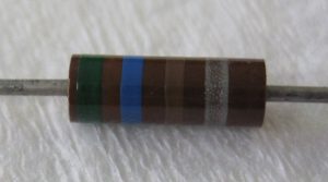
So I reduced R=560ohm -- and that worked, but the system would "freeze" after about 30 key-presses. These are the cheaper 5% resistors.

Reduced to R=470 ohm, and... so far, no problem!

For now, just replicating the "press 9" experiment, but it is all coordinated by software in the Nano.


1654397689454.png

There isn't much protection should one of these resistors fails closed (short-circuit?), but that's true elsewhere in this vintage system.

Here's the brief Arduino Nano code...

#define PIN_KBD_P 2
#define PIN_KBD_STROBE 11
void setup() {
pinMode(PIN_KBD_P, OUTPUT);
digitalWrite(PIN_KBD_P, LOW);

pinMode(PIN_KBD_STROBE, OUTPUT);
digitalWrite(PIN_KBD_STROBE, LOW);
}

void loop() {
pinMode(PIN_KBD_P, OUTPUT);
pinMode(PIN_KBD_STROBE, OUTPUT);

delay(60);

pinMode(PIN_KBD_P, INPUT);
pinMode(PIN_KBD_STROBE, INPUT);

delay(940); // wait out remainder of a second before next key-press
}

And a quick video to show it in action...


Next up is a full "interactive mode" to enter keys from some modern USB keyboard and have them translated into IBM 5110 scan codes.

Any suggestions on an easy way to inline a resistor into these 22 gauge wires, without soldering? :D
 
Back
Top