• Please review our updated Terms and Rules here

obscure system attached to a fluxgate magnetometer

1ajs

Experienced Member
Joined
May 27, 2005
Messages
452
Location
Winnipeg, Manitoba, Canada
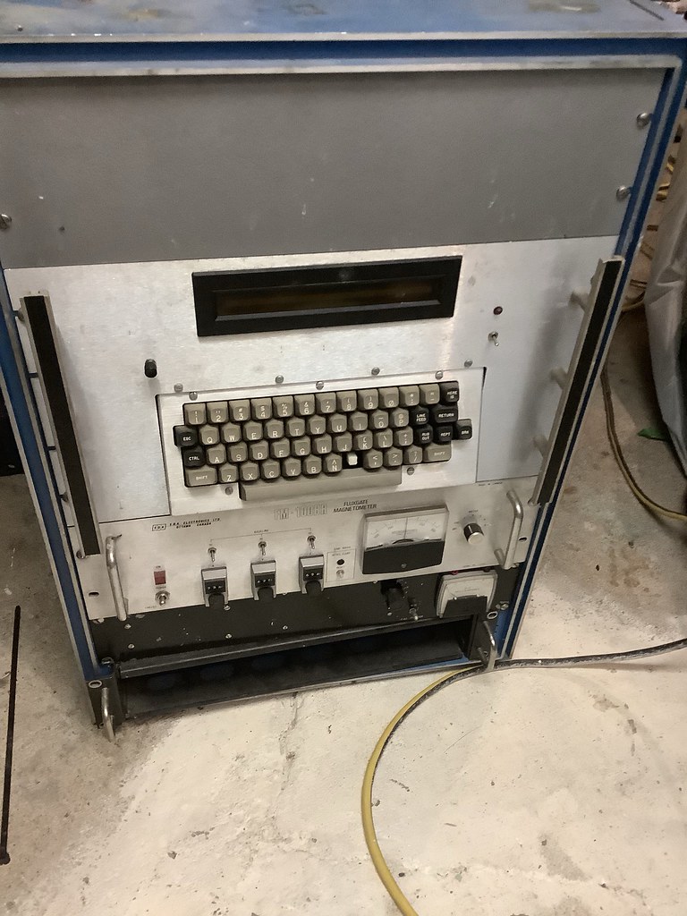
came across this system recently so i rescued it curious thing it is.

from discsions on the mailing list facebook and discord it is either part of a system that flew on planes looking for ore bodies oil and gas ect or was custom built for the usgs to mesure the magnetic feild of witch 6 systems where built that went around the world.
https://books.google.ca/books?id=Ja...=y#v=onepage&q=eda fm 100 br fluxgate&f=false

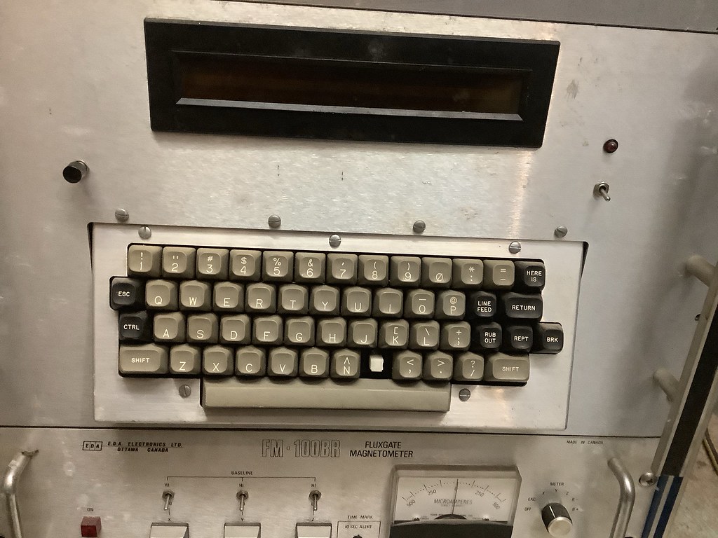
seeing the case in the rack its in u would think this was some beast but then when i opened it its a single board with a analog to digital converter mounted to it and a psu to one side plus a Keytronic keyboard on the front of it and display

50199901793_f074af16c0_b.jpg


117336970_10164163815850515_2738348470020419667_o.jpg


back side of the rack
50200714992_2f04e9ff31_b.jpg


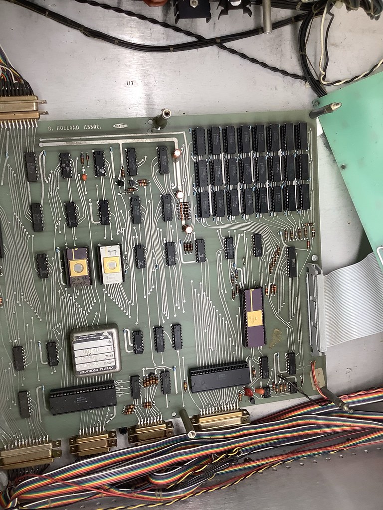
inside the computer case
50199903443_7c7caa4228_b.jpg


hidden under the DAC board is a motorola MC6800L cpu dated 76 and a cluster of mostek ram chips date codes of 1975 and 76. not sure whats on the intel eproms.
50200713557_7a258f66d0_b.jpg


inside the fluxgate box
117359537_10164164023960515_5696968730602901071_o.jpg


this is prolly one of the more obscure things ive come across and happy to give it a home.

the very bottom of the rack has something like a pdu controllor with a nob thats got 6 settings for different x and y z modes?
 
led's in my house

LED's have virtually 0 UV of any type. Florescences have some but not much UVC gets through the coating or the glass. Incandescences have almost 0 at the right frequency.
The EPROM would likely leak down 100s of times faster than any ordinary light. The energy needed to cause the tunneling that would erase the EPROM, requires a threshold energy level. If you don't understand that, look up "einstein photoelectric effect". Only photons of the right energy level will cause loss of data. LEDs have a sharp cutoff in frequency of the light emitted.
Dwight
 
What uP is it. It looks to be a Motorola. Is it a 6800?
It was clearly part of a larger system. All the terminal strips make that clear.
It is missing the flux gate coils. I'd guess they would be on a remote location. One can make flux gates with cores that are easily saturated. RF core often are easily saturated.
Dwight
 
Last edited:
What uP is it. It looks to be a Motorola. Is it a 6800?
It was clearly part of a larger system. All the terminal strips make that clear.
It is missing the flux gate coils. I'd guess they would be on a remote location. One can make flux gates with cores that are easily saturated. RF core often are easily saturated.
Dwight

yes a mc6800L

was all sorts of radio gear up here at one time. from us gov to cdn government to mining and exploration was something els im told.

what would i be looking for if the coils happen to still be laying around somewhere?

also im in a remote location at the edge of winter roads where ice road truckers was filmed and king of obsolete reins
 
I'm not real sure what you'd look for. I once took apart a dash compass apart to see how it worked. I was a two axis one. It looks like you'd have three separate sensors. What I had was a toroid that had a typical toeoid wind. This is the pulse coil that drives the core in and out of saturation. The fact that the winding goes all around the core means that the magnetic field caused by this winding never leaves the core. It is closed.
Around this were two windings at right angles. These windings were not toriodial windings. The windings went completely across and around the core. Since my flux gate was both E/W as well as N/S, it had two outside windings.
The way it works is that the toroidal wing is energized until the core saturates. When this happens, any external field does not see the core as magnetic. The filed lines just go by it as though it was a piece of air. As the current through the toroidial winding reverses, at some point, the core comes out of saturation. The external field now sees the core as a magnetic piece. The field lines all want to pull into the core. The field lines cross the outside winding to get there. This generates a voltage or current depending on the load. This signal has a strength that is related to the angle between the outside turns and the field as well the strength of the field. In my case, the two sense coils were vector added together to produce a compass direction.
I would suspect the sensors yours used to be three separate core assemblies. Most likely in plastic molded shape with non-magnetic mounts. These would likely have 5 wires. 2 for the sense coil, 2 for the pulse and 1 for the shield. It would surely have some arrow on it indicating the direction of the sense coil to field.
I hope this makes .
Dwight
 
Oh, it was just the quality of the response that engendered the concern. It wasn't typical of your style.

I'm quite dyslexic. I usually have to make several passes through my post to fix misspellings and completely wrong words. Sometimes I don't have time to proof read them and I miss a bunch.
I don't like the small quick reply windows as it is harder to reread through my post but I still use it. I often have to go back and edit post several times.
This page does better than I can, to describe the sensors:
https://www.sensorland.com/HowPage071.html
Still, now days, one can buy cheap solid state ones with all the electronics, except a couple resistors, for a few dollars. It no longer needs the larger boards used in this setup to have really good flux gate sensors.
Dwight
 
Back
Top