• Please review our updated Terms and Rules here

Odd KIM-1 fault from $280 to $29f

ClassicHasClass

Veteran Member
Joined
Mar 22, 2013
Messages
1,810
Location
(not so) sunny (No) So Cal
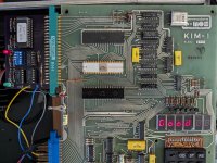
Was programming my briefcase KIM-1 last night when the program suddenly went awry. After trying to eliminate other causes, it turns out that the memory range from $280 to $29f suddenly had its upper six bits get stuck at zero.

It's only this range, however. $0080, $0180 and $0380 are normal, as is everything else in $0200. The RIOT RAM at $1780 is also normal, and the same fault is repeated at $2280, $4280, etc., as one would expect from the KIM's default 8K memory decoding. There are no cards connected.

Feels like a marginal component went bang but the fault seems unusually specific. Anyone got a guess? I thought about bad RAM, but it seems very weird it would be six at once, and limited to that specific range. The fault is also weird in that it's "aligned." Unfortunately everything on this Rev D board is soldered, so I'd prefer not to go mucking around on the board without a good idea where to start mucking around.
 
I'm not very familiar with the KIM, but maybe although the 6 bits are appearing as logic low, there might be some form of bus contention and they are say only just below logic low and maybe the other bits that are high are just above that that logic level and interpreted as high. So it "looks like" a pattern of 6 bits, but it isn't really and there might be some kind of global bus contention going on with all the bits in that address range. It would be interesting to look with the scope for anomalous logic levels on the address and data lines in that range, if you could get a small program to run to try to work that range. In other words one faulty IC could explain it or an IC on the bus affecting all 8 bits and responding when it should not.
 
Hmmm.....

One thing you could do to help with the diagnosis without having to remove any parts, since you know what address range is defective. You could cobble an address decoder together from some gates (or program a ROM is simple) and tack that onto the address lines. The purpose being to display a pulse that is active over that defective address range, as a pulse on one channel of the scope. Then on the other channel you could check some things such as whether the chip selects for the memory IC's might not be deploying or if there is a problem with the tri-state buffer on the memory IC outputs. At least then the scope would create a window into the timing where, or should I say when, it is malfunctioning.

(For my PET I built a diagnostic board that gave pulses for the address ranges of main RAM, video RAM and ROMs, which was a handy tool fault finding the board. I used a ROM, there is a photo of it on post #23 of this thread... https://forum.vcfed.org/index.php?threads/commodore-3016-scrambled-screen.1242960/page-2 )
 
You could try using an MCL65+ in place of the 6502 to perform some writes and reads while displaying results over the UART.
 
One thing you could do to help with the diagnosis without having to remove any parts, since you know what address range is defective. You could cobble an address decoder together from some gates (or program a ROM is simple) and tack that onto the address lines. The purpose being to display a pulse that is active over that defective address range, as a pulse on one channel of the scope. Then on the other channel you could check some things such as whether the chip selects for the memory IC's might not be deploying or if there is a problem with the tri-state buffer on the memory IC outputs. At least then the scope would create a window into the timing where, or should I say when, it is malfunctioning.

I did do a brute force stepthrough program.

Code:
*=$0000
r=$0280

        inc w
        lda w
        sta $f9
        sta r
        sta r+1
        lda r
        sta $fb
        lda r+1
        sta $fa

        jsr $1f1f
        jsr $1f6a
        cmp #$12
        bne *-8

        jsr $1f1f
        jsr $1f6a
        cmp #$15
        bne *-5

        jmp $0000

w       .byt 0

It turned out to be an artifact of the monitor that the upper 6 were clear. Actually, the stuck bit is entirely bit 2 (i.e., it goes

Code:
0 1 2 3 4 5 6 7 8 9 a b c d e f
0 1 2 3 0 1 2 3 8 9 a b 8 9 a b

and the high nybble is OK). Now a single bad bit sounds more like a faulty RAM chip and the 2102s are notorious for that, but why would it be just those addresses? Does that sound like a plausible failure mode? There are just 8 1Kbit 2102 RAMs, one for each bit.
 
Probably more like a contention on that bit over those addresses only. Otherwise it is hard to explain why that bit is working at other addresses. It would be interesting to see a scope recording of that bit when the address range was active.
 
Actually, I'm going to try to replace the RAM first. On cctalk a couple people pointed out that the row size on an SRAM chip this small could well be 32 bits, and the failure is precisely 32 bits on a 32-bit boundary, so the failure mode is plausible (bad internal driver or sense-amp). Since KIMs are notorious for bad RAM anyway, it makes the most sense to start there. This board has NEC D2102AL-4 SRAMs, so I ordered a couple MM2102AN-4Ls which look equivalent, and we'll see what happens.

If not, then I think I'll have to do the bigger debugging legwork like you suggested ...
 
Sounds plausible. It might be a case then, where paralleling another 2102 chip could cause it to recover. If you could prove that, if it worked, it would avoid any unnecessary de-soldering of an original chip from the board. Though in this case with just the 8k of memory and it coming down to the chip on that defective bit, it has already narrowed it down.
 
I piggybacked an NOS 2102 on U10 and got a proper byte. This doesn't work reliably but that could be because the RAM under it is malfunctioning, so time to clip out the chip and replace it, and see what misbehaviour is left. If this doesn't fix everything, the 74LS145 at U4 is next.
 
I clipped out U10, replaced it with a socket and put in a replacement 2102 of the same spec, but although the KIM will turn on, now it's just completely haywire (pressing RS over and over it sometimes come up normally and sometimes not, and even when it does some keys work only sometimes and then it just bombs out). I checked for shorts and buzzed out all the pins on the socket, and everything goes where it should and nothing leaks to adjacent pins, so I don't think it's my repair work. Another 2102, though same manufacturer, didn't fix it.

Instead of U4 I'm wondering about the buffers at U13 and U14, so I've ordered a couple of those and some sockets to try next. This really feels like RAM; I don't think the CPU or RRIOTs are bad with these symptoms. Wish I had one of Dwight's check boards.
 
Like a lot of these malfunctions, it requires a way, either with hardware or software or both, to craft a diagnostic system that can lead you in the right direction to identify the faulty chips.

When they are original period correct and date code correct IC's, soldered onto the board, in vintage valuable pcb's like KIM-1's or other computers of the era, it is a better idea to go with the notion that the pcb itself is the most valuable part.

It is often better to sacrifice the IC by clipping off its pins close to its body, before the pins are removed one by one (to save pcb damage) but, obviously, you don't want to do that unless the IC, has been proven on diagnostic testing, to be definitely defective, not just on a hunch that it might be defective.
 
(pressing RS over and over it sometimes come up normally and sometimes not, and even when it does some keys work only sometimes and then it just bombs out). check boards.
I don't have the KIM circuit at hand but that sort of thing suggests two possibilities that at least would be easy to exclude:

One could be that something has gone awry with the Reset system and its is getting multiple transients on the Reset line when released from reset.

The other could be some power supply noise issue. And that is upsetting normal operations after a good Reset.

The fact it sometimes comes up normally at least once is interesting, and is consistent with those things, and in the case of some poor power supply filtering, it could cause it to bomb out later after it successfully booted. I'm not sure what bypass capacitors are used near the IC's on the KIM's power rails, it can be worth a tacking a known good one like a 1uF MKT type across the CPU's power pins as a quick test, to make sure the problem is unlikely anything to do with transients on the supply.

Obviously there could be many other causes.
 
Back to this. I checked my work and found a couple dead lines without continuity that should be there on the schematic, but then all it did was go black and not do anything.

I got one of Dwight Elvey's debug boards, assembled it yesterday, and tested it with another KIM. It runs all tests and that KIM, which I wasn't sure was fully working, passes all tests with flying colours. So there's that. We can assume the debug harness is in working order.

When I plug the debug harness into this one, the dead board test passes (it blinks the green LED slowly), but it will not run the RAM test or any other test; it just sits there. The red ACCESS light glows like the CPU is doing something so it's probably not the 6502 but the green LED never turns on or displays a pattern.

Any guesses?
 
As stated in the instructions, If the RAM test doesn't pass, nothing else will work, I believe it is passing the cpu running test that blinks the light.
To run that test, all it has to do is boot from the boot address and execute, no RAM instructions.
The second test is the RAM test. The fact that that doesn't run is likely a problem with the address decoder. The fact that you have lines without continuity, would be the first place to fix.
If the board has been reworked, it is possible that feedthru's have been damaged or broken.
The RAM test it self only runs on internal registers in the CPU. It only expects addresses in the ROM to be read to run. If it isn't running, but the first test that just executes enough to blink the light, I'd say you have broken address lines some place. The RAM test uses quite a few address locations of the ROM, as compared to the first CPU test. It is possible for the first test to work and because of bad addresses for the RAM test to not even run.
Dwight
 
I checked my code. The CPU test uses A0 to A5 inclusive.
The RAM test uses the additional lines A6 through A8.
It uses the RAMs addresses but like I said, it doesn't use the RAM addresses to run code, only to write and read the bytes.
All the test use the boot address at FF?? ( boot address for 6502 ) or A15 and A14.
The boot vector is C000H, and run in the decoded to the 1K and I believe only uses the first bytes.
There is more code there but that is for code I put in to run one of Butterfield's KIM-1 games ( modified to run in the C000H block ).
The fact that it runs the CPU check means it is decoding C000H address, with the address decoder.
Dwight
 
OK!

I always hate it when I search and find a similar problem, but never find out what actually happened, so let's end this story. It's a happy ending.

- In the end there was only one bad RAM chip; it was bit 2, therefore U10.
- Buffers and address decoders were OK.
- Although I managed to restore all the continuity gaps (there were a couple lifted traces), the apparent dead board was because there was an intermittent short between two of the address lines - there's not a lot of space on the back of the board. I laboriously scraped away every bit of solder between those traces.
- The debug harness now runs all tests and all tests pass.

And now for a game of Wumpus in celebration. Eat my cans of happy gas, Wumpus.

Thanks to everyone for their suggestions (and to Dwight for designing the board). The moral of the story is, check your work. Then check it again. Then check it again. And maybe check it again after that.
 

Attachments

  • PXL_20230704_002401587~2.jpg
    PXL_20230704_002401587~2.jpg
    2.8 MB · Views: 7
Hi Cameron
I just looked at the email and saw your post there.
I thought I'd mention, a side effect of all the RAMs failing is that it will do alternating long and short pulses rather than showing all failing. That is because, when running out of the CPU registers only, there is no place else to store the results of multiple passes. The test patterns I use are two passes of 01010101 and 10101010. So, if all fail, it would stop at the first fail and display the alternating pattern, looking like half the RAMs were failing. When I wrote the test, I didn't consider what would happen is there was a 100% fail. One of the others, that bought the kits, told me about it.
The test that I have doesn't confirm the audio circuit, for cassette. I figure if one has the rest of the test I put in the ROM, it wouldn't be too hard to find the issues there with a scope.
I'm glad that the test board lives on. I just made the kits to cover the cost for the one I made for myself. My KIM-1 was in much worse shape.
There are a couple programs from Butterworth's book in the ROMs. I forget the address but they are someplace in the empty place of the first few couple of test. The one I like is the asteroids. You'd boot to the KIM's ROMs and then execute the address of the programs in the 1K window of the test ROM.
Many of the tests only use a small part of the ROM space. One can put a lot of programs in the empty spaces. I thought about putting Peter's Chess code in there but never got around to it. It would require loading parts into RAM and then, rather than just running out of RAM. It would require a little more than a single 1K space as well. All do able but I get distracted easily.
Dwight
 
Back
Top