• Please review our updated Terms and Rules here

Old eprom programmer help.

???

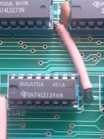
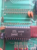
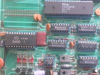
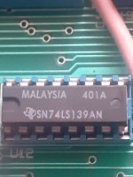
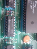
Can you post a photograph of the chip that you tested - including some surrounding components?

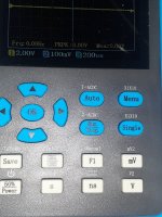
Can you also post the manufacturer and part number of your oscilloscope?

Dave
 
I ve found this sn74 ls139 coukd you confirm?
 

Attachments

  • 17070611654358117732660552026495.jpg
    17070611654358117732660552026495.jpg
    1.1 MB · Views: 3
U12 is another 139. We will be poking that next!

Keep looking for U7...

We also need to get your oscilloscope reading sensible signals...

Dave
 
D446c pin 4 5 6 7.
 

Attachments

  • 17070619256424287084345506592705.jpg
    17070619256424287084345506592705.jpg
    1.5 MB · Views: 2
  • 1707061983865649996220402133327.jpg
    1707061983865649996220402133327.jpg
    2.6 MB · Views: 2
I ve found another sn74ls139 near to z80 is it this one?
 

Attachments

  • 17070618095285774745565741271587.jpg
    17070618095285774745565741271587.jpg
    891.9 KB · Views: 3
  • 1707062208969252417174108252208.jpg
    1707062208969252417174108252208.jpg
    1.3 MB · Views: 3
Yes, that is U7.

Can't you see the white text "U7" near pin 1 of the IC?

I have no idea why you are probing the NEC D446C...

Let's see if your oscilloscope is adequate for measuring signals. Can you check the Z80 CPU (U2) pin 6. This should be a 4 MHz, 5V signal... Let's see what we can see...

Dave
 
Last edited:
Pin 6 z80.
Sorry for the delay.
 

Attachments

  • 20240204_175610.jpg
    20240204_175610.jpg
    1.6 MB · Views: 4
  • 20240204_175607.jpg
    20240204_175607.jpg
    1.5 MB · Views: 4
No problem. I was doing the washing up anyhow...

That is not what should be on pin 6 I am afraid...

What are the settings of your oscilloscope, both in the Y direction (Volts/div) and in the X direction (us/div)?

The signal should be a good 5V from peak to peak.

A 4 MHz clock signal has a period of 0.250 us or 250 ns, so I would set the timebase to 100 ns/div to start with (if you can get anywhere near that of course).

Dave
 
I tested the eprom 27128 some pictures.
 

Attachments

  • 20240204_182035.jpg
    20240204_182035.jpg
    1.3 MB · Views: 3
  • 20240204_181942.jpg
    20240204_181942.jpg
    1.4 MB · Views: 3
  • 20240204_181857.jpg
    20240204_181857.jpg
    1.4 MB · Views: 3
Those signals don't make any sense either I am afraid...

You need to set [1] to 1 V/div with your oscilloscope probe set to X1.

You need to set the oscilloscope to single channel (not dual as you have it).

You need to set [H] to 100 ns/div if possible.

Dave
 
Last edited:
Ok i set it at 100 ms now this is what i get.
 

Attachments

  • 20240204_183521.jpg
    20240204_183521.jpg
    2.5 MB · Views: 5
  • 20240204_183522.jpg
    20240204_183522.jpg
    2.2 MB · Views: 5
[AUTO] (on the top left) refers to the trigger mode. If there is an auto mode fir configuring the X and Y axis I wouldn't trust them!

Dave
 
I could nt find any other settings of x and y.
 

Attachments

  • 20240204_185353.jpg
    20240204_185353.jpg
    2.4 MB · Views: 4
That's looking much better!

I would still change [1] to 1 V/div and move the 0V reference down below the centre line. This will fill as much of the screen as possible.

Set your probe to the GND setting (if this is an option on your probe) and then adjust the oscilloscope trace so it is 1 division up from the bottom of the screen. Set your probe back to DC.

By the way, you have set the timebase to 100 ns/div not 100 ms/div - but what are a few zeros between friends!

You still appear to have the 10X probe setting set? This should be X1 for the time being.

Dave
 
Last edited:
>>> I could nt find any other settings of x and y.

You press the V and mV buttons to adjust the Y setting.

You press the s and ns buttons to adjust the X setting.

Multiple presses of the same button causes the range to keep changing further...

Dave
 
Back
Top