Not sure if there is a way to check the Extra high-tension transformer, after doing a double check on the voltages in G1 and G2 any other advice Hugo?I agree .
Both the focus and G2 voltages are sourced from the EHT, the focus potential could be 5kV or more and the G2 maybe around 500v. Also, the G2 being in the lower leg of the voltage divider, the source resistance there is unlikely to be more than a few Meg Ohms, so if it only reads 80V with a typical DVM (that has a 10 Meg input resistance) this implies that the EHT itself must be very low (assuming the voltage divider chain has not failed). And one would expect the CRT to be blacked out.
- VCF South West - June 14 - 16, Davidson-Gundy Alumni Center at University of Texas at Dallas
- VCF West - Aug 2 - 3, Computer History Museum, Mountain View, CA
- VCF Midwest - Sept 7 - 8 2024, Schaumburg, IL
- VCF SoCal - Mid February 2025, Location TBD, Southern CA
- VCF East - April 2025, Infoage Museum, Wall NJ
-
Please review our updated Terms and Rules here
You are using an out of date browser. It may not display this or other websites correctly.
You should upgrade or use an alternative browser.
You should upgrade or use an alternative browser.
Old monitor Acerview 11vga
- Thread starter Datamisc
- Start date
It does look a lot more like mine. will check it and post my results. Thanks Burley.Here is the complete 7033 manual.
Hugo Holden
Veteran Member
One of the best places to check the health of the H output stage & flyback transformer, is the collector waveform on the H output transistor. The thing is, while the flyback peak there in smaller monochrome VDU's is only in the order of a few hundred volts, in the color VDU it can be in the order of 1000v or a little more. So it requires a x100 probe to be used with the scope. Most of these probes are rated to 2kV, at least now they are cheap on ebay.Not sure if there is a way to check the Extra high-tension transformer, after doing a double check on the voltages in G1 and G2 any other advice Hugo?

100X P4100 High Voltage 2KV 2000V Oscilloscope Scope Passive Clip Probe 100MHz | eBay
Model: P4100. System bandwidth: DC 100MHz. Input capacitance: 100X (6pf). Attenuation: 100X. 1 x Probe (cable length: 120cm). Material: Plastic- Input resistance: 100Mohm. Compensation range: 10pF~35pF.
www.ebay.com
Thank you, I have ordered the probe. Will double check voltage in G1 and G2 meanwhile.One of the best places to check the health of the H output stage & flyback transformer, is the collector waveform on the H output transistor. The thing is, while the flyback peak there in smaller monochrome VDU's is only in the order of a few hundred volts, in the color VDU it can be in the order of 1000v or a little more. So it requires a x100 probe to be used with the scope. Most of these probes are rated to 2kV, at least now they are cheap on ebay.
100X P4100 High Voltage 2KV 2000V Oscilloscope Scope Passive Clip Probe 100MHz | eBay
Model: P4100. System bandwidth: DC 100MHz. Input capacitance: 100X (6pf). Attenuation: 100X. 1 x Probe (cable length: 120cm). Material: Plastic- Input resistance: 100Mohm. Compensation range: 10pF~35pF.www.ebay.com
Any other thing I have to check that I have missed?
Have a good weekend guys!
Ok I got the High Voltage Probe and measured the only transistor I could find in the power PCB, the K793 high voltage N-MOSFET with the following results
Gate:

Drain:

Source

Also did a double check on the G1:

And for G2, I checked the power coming from the EHT:

And once it got to G2

The following are pictures of the power PCB :

and the CRT PCB

As always thank you guys for help me out.
Any suggestions will be appreciated.
Gate:
Drain:
Source
Also did a double check on the G1:
And for G2, I checked the power coming from the EHT:
And once it got to G2
The following are pictures of the power PCB :
and the CRT PCB
As always thank you guys for help me out.
Any suggestions will be appreciated.
bburley
Experienced Member
Your G2 voltage does seem a bit low. In this article, which may be helpful, it shows a typical G2 voltage of 400V - Understanding the Operation of a CRT Monitor
Hugo Holden
Veteran Member
"Ok I got the High Voltage Probe and measured the only transistor I could find in the power PCB, the K793 high voltage N-MOSFET with the following results"
Gulp !
The power pcb contains the line voltage power supply. This system, on the primary side of the power transformer has no common electrical relationship to the VDU's secondary power supply system. It is isolated from it by the power transformer by magnetic induction and insulation between the primary and secondary windings, even signals sent back to the primary side, from the secondary side, for feedback control are sent either by transformers or opto-couplers to maintain the isolation.
If you attempt to make a scope measurement on the primary side, with the scope earth clip on common (the chassis or the secondary side) you will just see high voltage 60Hz sine waves. To be able to measure with a scope, on the line side of the power supply where the switching mosfet is, you would require an isolating transformer and a good knowledge and experience of how SMPS supplies work and where to safely clip the scope's earth clip. Luckily, in this case the x100 probe saved the day, if it was just a x10, connected that way, it could have failed & caused problems.
Keep well away from the line side of the power supply.
The place to check the flyback waveform, with the x100 probe, is on the collector of the H output transistor. It would pay to read up on what sort of waveform you would expect to see there, both in the expected amplitude and shape of the wave.
andy
Experienced Member
Have you tried turning up the G2? As said before, with only about 100v on the G2, I would expect to see no picture.
Thanks for the Explanation Hugo, this is my first time with a CRT monitor and between all your help and things I read I am slowly learning the works of it."Ok I got the High Voltage Probe and measured the only transistor I could find in the power PCB, the K793 high voltage N-MOSFET with the following results"
Gulp !
The power pcb contains the line voltage power supply. This system, on the primary side of the power transformer has no common electrical relationship to the VDU's secondary power supply system. It is isolated from it by the power transformer by magnetic induction and insulation between the primary and secondary windings, even signals sent back to the primary side, from the secondary side, for feedback control are sent either by transformers or opto-couplers to maintain the isolation.
If you attempt to make a scope measurement on the primary side, with the scope earth clip on common (the chassis or the secondary side) you will just see high voltage 60Hz sine waves. To be able to measure with a scope, on the line side of the power supply where the switching mosfet is, you would require an isolating transformer and a good knowledge and experience of how SMPS supplies work and where to safely clip the scope's earth clip. Luckily, in this case the x100 probe saved the day, if it was just a x10, connected that way, it could have failed & caused problems.
Keep well away from the line side of the power supply.
The place to check the flyback waveform, with the x100 probe, is on the collector of the H output transistor. It would pay to read up on what sort of waveform you would expect to see there, both in the expected amplitude and shape of the wave.
Will search for the H output transistor and will measure it then.
Hey Andy, thank for the reply, I've read about desoldering the G2 wire and doing direct measures on it. Should I do that first or adjust the G2 knob first and how much voltage do you recommend?Have you tried turning up the G2? As said before, with only about 100v on the G2, I would expect to see no picture.
Interesting article, thank you Burley, will read it also tomorrow so my head gets all the important things.Your G2 voltage does seem a bit low. In this article, which may be helpful, it shows a typical G2 voltage of 400V - Understanding the Operation of a CRT Monitor
andy
Experienced Member
It's not a critical adjustment. Just turn it up and see if you get anything on the screen. If there's no difference, put it back where it was originally. Regardless of what voltage is on the cathodes, turning up the G2 will usually produce some kind of raster. What you see could be helpful. Or, if your previous measurements were correct, the G2 being very low could explain the lack of a picture.Hey Andy, thank for the reply, I've read about desoldering the G2 wire and doing direct measures on it. Should I do that first or adjust the G2 knob first and how much voltage do you recommend?
To measure it, just use your DVM. There's no need to disconnect the wire from anything. It's an adjustment that affects the brightness of the image. For final adjustment, you set the brightness control at mid range, and adjust the G2 for normal brightness.
Will do that and post here my results. thanksIt's not a critical adjustment. Just turn it up and see if you get anything on the screen. If there's no difference, put it back where it was originally. Regardless of what voltage is on the cathodes, turning up the G2 will usually produce some kind of raster. What you see could be helpful. Or, if your previous measurements were correct, the G2 being very low could explain the lack of a picture.
To measure it, just use your DVM. There's no need to disconnect the wire from anything. It's an adjustment that affects the brightness of the image. For final adjustment, you set the brightness control at mid range, and adjust the G2 for normal brightness.


bburley
Experienced Member
You don't have any horizontal deflection. Need to check components and voltages/waveforms around the yoke.
andy
Experienced Member
Since the horizontal deflection is driven by the same circuit that drives the flyback, you can be sure most of it is working since you have high voltage. One side of the horizontal yoke winding should connect to the collector of the HOT. The other side will pass through various components on its way to ground. Some simple resistance checks, or visual inspection should locate the problem. Also make sure the horizontal yoke winding isn't open.
Be sure to turn the G2 back down to avoid burning a spot in the middle of the screen.
Be sure to turn the G2 back down to avoid burning a spot in the middle of the screen.
So, this repair is not only to make the monitor work, but I also love to learn new things. I could not find the Horizontal Output Transistor, as much effort I gave, it was supposed to be near the Flyback transformer, but my inexperienced eyes just didn't saw it. After much investigation about that particular transistor got to a page that mentioned a snubber capacitor that is purposedly the protector of such transistor, after seeing a picture of that capacitor I finally located the HOT, it is using the shield of the Flyback transformer as heat dissipator, in a corner, and that is why I could not see it."Ok I got the High Voltage Probe and measured the only transistor I could find in the power PCB, the K793 high voltage N-MOSFET with the following results"
Gulp !
The power pcb contains the line voltage power supply. This system, on the primary side of the power transformer has no common electrical relationship to the VDU's secondary power supply system. It is isolated from it by the power transformer by magnetic induction and insulation between the primary and secondary windings, even signals sent back to the primary side, from the secondary side, for feedback control are sent either by transformers or opto-couplers to maintain the isolation.
If you attempt to make a scope measurement on the primary side, with the scope earth clip on common (the chassis or the secondary side) you will just see high voltage 60Hz sine waves. To be able to measure with a scope, on the line side of the power supply where the switching mosfet is, you would require an isolating transformer and a good knowledge and experience of how SMPS supplies work and where to safely clip the scope's earth clip. Luckily, in this case the x100 probe saved the day, if it was just a x10, connected that way, it could have failed & caused problems.
Keep well away from the line side of the power supply.
The place to check the flyback waveform, with the x100 probe, is on the collector of the H output transistor. It would pay to read up on what sort of waveform you would expect to see there, both in the expected amplitude and shape of the wave.
The transistor BU1008ADF
After all that I finally get the Oscilloscope readings:
Pin 1:

Pin 2:

Pin 3:

On a side note, when my oscilloscope probe first touched the pin 1 of the transistor, for a split second I heard the sound of the image being displayed on the screen; a friend (helping me take pictures from the oscilloscope) said he saw a quick image which disappeared fast.
Not sure if that was a bad thing or a good thing.
Thank you all again for the help.
bburley
Experienced Member
The waveform from pin 2 (Collector) looks low. It should look closer to this;

I would have expected to see a smaller 31KHz waveform on the base of Q312 coming from the driver transformer, but it doesn't seem to be there or your scope probe connections are not right or something caused the signal to disappear when you connected.
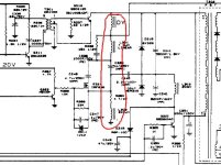
You haven't indicated how close the schematic in the last manual that I uploaded actually is to your monitor, but you need to check some components in this area;

I would have expected to see a smaller 31KHz waveform on the base of Q312 coming from the driver transformer, but it doesn't seem to be there or your scope probe connections are not right or something caused the signal to disappear when you connected.
You haven't indicated how close the schematic in the last manual that I uploaded actually is to your monitor, but you need to check some components in this area;
Ok will triple check with the oscilloscope and will analyze the schematics for that area. Thank you Burley..The waveform from pin 2 (Collector) looks low. It should look closer to this;
View attachment 1279039
I would have expected to see a smaller 31KHz waveform on the base of Q312 coming from the driver transformer, but it doesn't seem to be there or your scope probe connections are not right or something caused the signal to disappear when you connected.
You haven't indicated how close the schematic in the last manual that I uploaded actually is to your monitor, but you need to check some components in this area;
View attachment 1279040
andy
Experienced Member
I think you're over analyzing this. The fact that you have high voltage means the HOT is doing its job. There isn't much that could fail to cause no horizontal deflection, but still have HV. With the horizontal yoke out of the circuit, the signal on the collector of the HOT will definitely be low, as well as the HV, and other voltages that come from the flyback.
Some simple resistance measurements will almost certainly quickly locate the problem. The failure is probably one of the components I have circled. If all of those parts were good, you would have at least some horizontal deflection. It's also very likely to be a mechanical problem like a cracked trace, or bad solder connection.
Some simple resistance measurements will almost certainly quickly locate the problem. The failure is probably one of the components I have circled. If all of those parts were good, you would have at least some horizontal deflection. It's also very likely to be a mechanical problem like a cracked trace, or bad solder connection.
Attachments
Last edited: