• Please review our updated Terms and Rules here

Original Tandy 1000 no boot

I'm not sure how it is on other machines, but the Tandy 1000's are able to operate the keyboard lights independently, at least for a while. When I had a blown '245 on my HX, I was able to toggle the numlock and caps a few times before the keyboard controller locked up. That '245 buffer was on the data bus by the expansion header - half the gates were bad, and was causing the entire bus to lock up while the address lines kept going.

I think the IBM XT had a 4.77MHz processor, same as the 1000. Are you able to swap the CPU from your XT?

Interestingly the 245s are among the few chips that are socketed. But I have swapped those with others I have and no effect. The only thing that changes things at all seems to be pulling either the CPU or PIC.. if those go the snow changes into lines.

I have checked the voltages after 5 minutes of run time.. they are all well within spec.
 
Are you pulling the CPU/PIC outright, or swapping them with a known working unit? Which chip number is the PIC you're pulling? I want to follow along on the schematics.

Can you post pictures of the display during these two states, and tell me which video output you're using? Snow is rather unusual on an RGB display, unless you're referring to random ASCII characters.
 
Pulling them outright, for that particular 'test'.

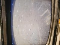
This is the screen I usually get, on composite, on power up, with all chips installed. These dots all move around continuously, there is no reaction to Reset or anything, and nothing onscreen whatsoever off the RGB regardless.

20191124_193101.jpg

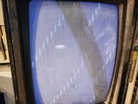
If I pull the 8088 or PIC out completely and power up, I get this screen:

20191124_193231.jpg

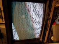
And every once a while, randomly, I get a screen like this:

20191124_193138.jpg

This screen reacts to Reset.. changes intensity for a second before coming back to bright white.

All of this could be meaningless - but this random video out the composite is the only sign of life there is. That and the continuously shrieking speaker.

When I first got it it was fully working except for a continuous 'busy' light on the floppy drive, with no disk reading. I pulled the FDC first and cleaned the pins, no change, then pulled the drives and tested in another machine. They were fine. So I tried another cable I had lying around.. nothing. And then on one power up, suddenly that speaker shriek and nothing onscreen again.
 
Oh, and I should mention I have tested the 8284 and CPU in my XT.. they both work fine there. Also have swapped RAM around (haven't tested it in another device or board yet though) without any change. I've tested the BIOS ROM in a 1000EX I have, so that all seems good.
 
The first picture looks like a cursor on an HSYNC signal that's gone way off kilter (to me anyways)

You've already tried swapping the CPU and the 8284 from the 1000 into a known working system, and they're working, so those are out of the way.

This all happened after you took everything apart and cleaned it? Just to make sure, is the E5-E6 jumper from the oscillator installed?

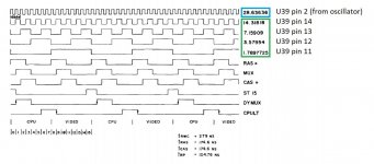
U39 is a binary counter which takes the 28.6 MHz signal from the main oscillator, and feeds the 8284 it's 14.3 Mhz clock signal, as well as the 3.6 MHz signal to the tone generator. Maybe use the oscilloscope to verify the frequencies off of U39 pins 11,12,13,14, and coming in at pin 2 from the oscillator, according to the following timing diagram from the technical manual.
1000 clocks.jpg

If these are proper, then we can move on down the list.
 
Hmmm... the signals do seem to be a fair bit off... at least, if I'm using this thing right. Seem to be at 12MHZ where there should be 14.1 and on down. Incoming looks right.

74F161... can that be substituted with a 74LS161? Not sure what the F means. I have LS161s not but F.
 
Last edited:
Hmmm... the signals do seem to be a fair bit off... at least, if I'm using this thing right. Seem to be at 12MHZ where there should be 14.1 and on down. Incoming looks right.

74F161... can that be substituted with a 74LS161? Not sure what the F means. I have LS161s not but F.

Yeah, I think the 74LS161 should work as a drop in replacement. The F series looks to be discontinued, but that's not surprising. The LS and HCT series seem to have taken over most applications.

The video array is timed by the 14MHz clock signal, so if that's running closer to 12, that would explain why the horizontal sync is wonky. Somehow, it's also supposed to reduce that 14MHz into 15.7 KHz, which would also render the V-Sync on the RGBi output as out of spec.

Well, fingers crossed, that's all it is.
 
Finally solved this. A trace accidentally got cut when one of the drives fell and struck the motherboard. Took me this long to find it.

So im back to my original problem.. it won't boot. Drive A spins and lights, stays that way. No actual effort to read anything. Boot msg just says insert disk to boot.

The machine came with two Toshiba 360k drives attached via a short blue ribbon cable. However looking at it now, I can see that cable had to be backwards.. pin one at the header end is on the opposite side of pin one on the drives, and the cable was not folded over on itself to orient. So I don't know how this ever would have worked.. unless I'm forgetting something about Tandy drive setups.

But yeah, the drive doesn't init, and I've tried the cable backwards and forwards and it seems to make no difference.
 
The original, short floppy drive cable was only designed to work with the TEAC drives that Tandy equipped with the 1000s. It has no twist between the A and B drive connectors, and the colored stripe is on the pin 34 side of the cable, not the pin 1 side! To use any other brand of floppy drives with it, you'll need to replace the cable with a longer, more standard one.
 
Yeah, I don't think the cable it came with is original:

https://drive.google.com/file/d/1kPcakUC6QnCVO8BgkGYZEuizftQztIRg/view?usp=sharing

If you look really closely you can see the connectors' pin 1 is on the same side as the striped wire. The machine came with that cable and two Toshiba FDD5401 floppy drives. I don't know how it could have worked.. the way it appeared to be set up, pin 1 of the header connector was plugged into pin 34, and then pin 1 of each drive connector was into pin 1 of each Toshiba drive. I don't see any evidence the cable was folded or anything to allow aligning the header to pin 1 properly.
 
Come to think of it, maybe this cable is correct. The TEAC drives have their PIN 1 on the opposite side that the Toshibas and most other drives do.. so even if you plugged this cable in 'wrong' with the striped wire connecting to PIN 34, it would still be correct as 'pin 34' on this cable would now actually be pin 1.. weird way to do it though.
 
Not sure why the cable didn't come with a key so that you don't plug it in backwards (though you could still connect it backwards at the motherboard header), but whatever.
Does the drive just stay spinning all the time, or only when you try to access it?
Could you give us the model number of the drives, as well as list what the jumpers on both are set as? I'm wondering if maybe somebody didn't knock a jumper loose by accident. The drives should be jumpered as DS0 and DS1 (for A: and B: respectively), and the motor control jumper should be set to MS instead of MM (to use the Drive Select signal), since Shugart controllers only use one motor control line (pin 16)
 
Many thanks.. I will dig out this info tomorrow.

Basically what happens is you power on, and drive A immediately lights up and the motor spins. It does not react or change in any way as the machine goes through its post cycle.

Thinking about it now I'm not sure how this set up could ha e worked. As I recall the cable was lined up straight, so pin 1s and 34 would have gotten reversed by the time they got to the drives. But it does look like they were installed for some time.

I am looking around for a TEAC replacement.. prefer those with Tandy. Just trying to figure out which model they used.. think it was FD-55B or B-U?
 
If the light comes on and the motor spins endlessly as soon as it’s powered on that’s the classic sign of the floppy connector being plugged in backwards. I’m a veteran of having done that more than once on my TRS-80s and the Tandy 1000 uses the same Shugart wiring scheme.
 
If the light comes on and the motor spins endlessly as soon as it’s powered on that’s the classic sign of the floppy connector being plugged in backwards.
Done that myself more than a few times. Especially confusing on Tandy's 3.5" drives, because the key notch is on the opposite side of the connector.

If both drives are spinning right on startup, then reversing the connector on the motherboard so that pin 1 on the header lines up with pin 1 on both slot edges ought to fix that problem. If this is happening only on one drive, then it's probably a jumper issue. Might be a good idea to snap photos of the jumpers on both drives and give each a temporary label before we go messing with them.

the Tandy 1000 uses the same Shugart wiring scheme.
I wonder why Tandy decided to keep up with the Shugart scheme long after they abandoned the external floppy port. Probably made comparability easier within their own product lines, but it makes things a pain if you're trying to use third party 3.5" drives. It's not just the original 1000, but as far as I can tell, they used it right to the end of the line with the RSX, as I stumbled upon when I had to replace my RSX's floppy. Not sure about the other Tandy lines, but I know the 2500RSX is basically the same motherboard as the 1000RSX, so they might have even done this for all of their systems.
 
I have tried orienting the cable both ways.. being careful to make sure pin 1 on the header connects to pin 1 on the drive results in what I described: drive A spinning endlessly. If the cable.is reversed, both drives light but don't spin.
 

Right away I notice that the drive set as DS2 (seems they start at 1 instead of 0) is missing a bunch of jumpers from PJ5. That's probably for the terminator resistor pack (the white chip between the jumper blocks). Like SCSI, the terminator would be enabled on the last drive on the cable. If drive 1 was at the end of the cable, that should be fine, though it probably ought to have another jumper across position 1 too, if that's what it is.

I can't find an exact match for FD5003, but I found a PDF that appears to have similar jumper configuration on page 2: http://blog.3b2.sk/igi/file.axd?file=2015/5/5.25-jumpers.pdf
Based on that, both drives are set to have the LED come on when the drive is selected, rather than by the "in use" signal, and the heads are loaded by the "motor on" signal rather than "drive select."
The jumper for RM/DM doesn't appear to be populated on either, so I don't think that's the cause.

I see test points sticking up from the board. Maybe check between the "RY" test point (between C10 and C11) and ground with a multimeter, and see if the state changes when you try to access the drive.

Before going further, I'd stick a label on both drives so you can tell them apart. I'm thinking that if populating the T1 position of JP5 doesn't solve the problem on the A: drive, then try populating the JP5 block on the B: drive and setting it to DS1, then try to boot from that with only the one drive. If you can boot that way, and the drive behaves normally, then we'll know it's something with the drive and not the controller.
 
Ok many thanks.

Just FYI - I've also tried this with a 360K panasonic drive from a Commodore PC10 that does exactly the same thing. I'll have to get a pic of the jumpers but it worked fine as an A drive in other machines, and the Toshiba configured as A has worked in other machines also.
 
Back
Top