• Please review our updated Terms and Rules here

Osborne OCC1A won't boot from floppy A, B, or GOTEK

booboo

Experienced Member
Joined
Sep 13, 2009
Messages
172
Location
Dallas, Texas, USA
Seeking some ideas, as I've run out of options here...

Symptom: Osborne will not book any disk image from Gotek or floppy disk from drive A or B.

Background: I have a (new to me) Osborne OCC1A, with factory DD board and a Nuevo 80 column card. ROM 1.51. When booting, it seems to load track 1 and 2, then either:
  1. Stops reading disk or Gotek
  2. Spins disk or Gotek
  3. Prints garbage on the screen
Diagnostic Steps Taken:
  1. Removing the DD and 80-column options and installing ROM 1.44 makes no difference.
  2. Replacing the Z-80
  3. Replacing the Fujitsu FDC chip
  4. Booting from A, B (Shift "), and from a Gotek.
  5. I've tried the CP/M images Retrocmp (SSDD and SSSD).
    1. All exhibit some fashion of the same issue., in that there's no BOOT ERR but rather it loads just track 1 and 2 (according to the Gotek display)
    2. Trying to boot a blank disk DOES give a BOOT ERR message, so it's correctly interpreting a boot track/loader
  6. Same effects with floppies created with IMD or TELEDISK
    1. Floppies created on a 386 booted with MS-DOS 6.22, using a 360K Tandon or 360K Mitsubishi floppy drive
    2. Blank floppies are 360KB DD
  7. Powered the system board using an external power supply (ATX with a custom dongle) supplying ample +5 and +12VDC
  8. Checked that RAM is getting 5VDC
  9. Only chip that is marginally warm is the video RAM and system RAM, but not hot
I'm suspecting either RAM or some other issue that manifests after I try to use more that minimal RAM for a power on. It reliably powers on...

Thoughts?

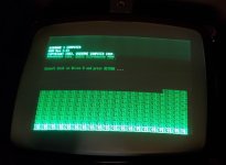
Sample screen but always changes....380219644_10227758678140185_831318908431196939_n (Small).jpg
 
Thanks cj7hawk for reviewing. Yes, I mentioned on diagnostics item 3 above, the Gotek shows the Osborne first reset the drive (seems to quickly mode the 'head' across the drive) then read Track 0, then Track 1, then stops in Track 2, Cyl 0. I was off above. it always does this... in CP/M are Tracks 0 and 1 a boot loader?
So then, if it's RAM, how do I diagnose further? I don't have a Fluke Z80 logic analyzer :( Does ROM 1.0 work on this system board and does it provide enough diags to check RAM? I don't seem to find ROMs older than 1.3.
 
When you Power UP and Boot the Floppy Drive Spins, the head steps from it current position
to track 0, the TRACK 0 Sensor sends the Floppy Disk Controller a signal that the head is at
Track 0, and the Index pulse is telling the FDC that the Floppy is rotating. If these Signals
aren't getting to the FDC, the Floppy drive just sits there.

You can manually move the Head carriage assemble to it's center position with power off, then check
that it does move to Track 0, and gives the Track 0 Signal, along with the Index Signal to the FDC.

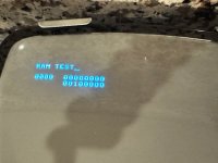
Another interesting thing is the repeating characters on the display. The ")" is repeated every 5th
Character, so 4 are repeating and 2 ^ 2 = 4. I'd have a look at Address Line A2 making sure it
isn't stuck HIGH.

Larry
 
Another interesting thing is the repeating characters on the display. The ")" is repeated every 5th
Character, so 4 are repeating and 2 ^ 2 = 4. I'd have a look at Address Line A2 making sure it
isn't stuck HIGH.
Larry
Thank you! To be clear that screen changes all the time... As I've changed the Z80 already, when you say check A2 you mean the 74 logic after the Z80 but before the RAM? That line seems to move via a 74LS153 and a 74LS244, then to the RAM.
 
You say the screen changes. But is the pattern of repeated locations the same character (even though it changes) after next power off/on? So not the same actual character but the same repeated locations?
 
You say the screen changes. But is the pattern of repeated locations the same character (even though it changes) after next power off/on? So not the same actual character but the same repeated locations?
No it's completely different (sorry if not clear, I mentioned this in the first post). Sometimes it will reboot, sometimes it will print a similar screen, sometimes it will show snow on screen, sometimes no additional text. I cannot get it to show the same behaviour on demand...
 
Something is preventing normal execution, but clearly the ROM is being read and is executing OK. If it appears to be loading or trying to load something, then it is likely failing to on some code that it is executing.

You could add a logic analyzer and don't need a fluke. Hanteks are pretty cheap at a few hundred and would tell you what is executing and what instruction it's executing, but you could even go with a small 8 channel Salaea logic analyzer that costs about $15-$50 for clones and originals....

You will need some tools to attempt deep repairs on any computer PCB but there is some stuff you can do first.

Check your extra voltages are present and correct on the 4116's. -5v on pin 1, 5v on 8, 12v on 9 and Gnd reference on 16.

Once you've confirmed these are all correct and stable, you can try looking for one that gets hotter than the others - that's a good indicator, but can be difficult to detect. Generally you want an oscilloscope to examine the signals.

As was mentioned, you want to make sure the signals are all correct. A 8 channel logic analyzer can help if you get down to the signal level on supporting logic ICs.

Also, don't forget writing your own diagnostics rom can help... A bit of programming and reading/writing memory to see what is going on, and you can write the Osborne display in the last 4K of memory, though keep in mind it doesn't display anything, so repeating any messages every 64 bytes will ensure that the message is seen one way or another, and you could write a quick RAM diagnostic program. Or you could write a basic bootloader for a GOTEK and use that to insert executing code. Keep it small and simple too.

You can sometimes piggyback a RAM chip to find a fault, and there might be a floating RAM data line that is changing enough through induction or leakage to reflect a signal ( eg, an address line ).

Having a working board as a reference is another helpful way to solve the problems. But as long as you have a video signal or other way to output information, you're already ahead - :)
 
Hi @booboo ,

I saw your reply, but for some reason it's not showing up here... A normal logic analyzer is sufficient for most repair work - they give 8 lines and operate at around 24 MSPS, which is enough for a 4MHz z80.
A full processor analyser would be better, but is not needed. A cheap one will do.

Can you give an idea of your technical skills? I'll write some quick questions;

1) Can you program in z80? - Do you have an eprom programmer and some 2732 eproms? If so, you can write some basic diagnostic software.

2) Do you have a multimeter? You can check your voltages are all OK and check continuity later.

3) Do you have a logic analyzer? These work OK for basic tests: https://www.ebay.com/itm/155486357723

4) Do you have an oscilloscope? Anything over 5Mhz / 25 Msps is OK. How many traces?

5) Are you familiar with how a z80 operates?

6) Are you familiar with the Osborne Architecture?

7) How are your Soldering and Desoldering skills?

8) Are you familiar with the "Piggy Back" method of testing RAM?
Thanks @cj7hawk for the follow up, I hadn't reply to the previous note yet. Here's my status, haven't had any time to retake this project last couple of days. To your bulleted points:
  1. It's been a long time, so not proficient at all in assembly. Yes, I do have an EPROM programmer and spare EPROMs, that's how I made the test 1.44 ROM to see if I had some some compatibility issue. I was asking about ROM 1.0 as I understood that initially Osborne provided diags on the built in ROM. However I've not had any luck locating such a version. I also saw a post of a user making such a test device using custom software and a MZLC8, but I don't really want to build such a device as it would require ordering custom boards, etc.
  2. Yes, and in the OP I mentioned that voltages seem good, and I've also tested with an ATX PS using a custom harness (to eliminate the old PS)
  3. I've ordered a logic analyzer, so that's in the plan to see if I'm getting sensible traffic or to see if there's some stuck line
  4. No scope, will be getting one soon
  5. Elementary understanding of the z80 but not enough to to write the ROM diags
  6. Same
  7. Good to excellent skills soldering and desoldering, but do want to limit the amount of work on the board; e.g. ideally need to find the right RAM or 74 logic to replace. Really wish this board was fully socketed like a Kaypro :)
  8. Yes. I've already tried that, using a known good RAM DIP from an Apple ][ I tried to boot the system using a piggyback RAM (a boot at a time) and no improvement. I know this is not conclusive, and was just the boot as I cannot currently run a diagnostic suite.
 
Sounds like you have most of what you need. It will also help others who pipe in and know more than me to know what to suggest. The bad news is that I can't get all the answers either. I am not an expert on the Osborne 1 architecture.

Reprogramming the Eprom seems the easiest. I have 1.2 as earliest, which says "monitor" but I can't see anything in there about debug. It might be something I don't know about.

Video is fixed in memory and if you check the tech manual, it starts with Bank 2 installed ( ROM ) from a reset. It seems that all I/O is memory mapped and any OUT commands are used to switch banks, and apparently it's possible to create bus contention with an out. I think it's the out address that switches banks rather than the value in A since the code in the boot rom begins something like this;

out (3),A
JP 0036

0036:
di
ld sp,EFC1h
xor a
ld (EF69h),a
ld (EF17h),a
ld (EFEFh),a
call 0085h
ld hl,ED00h
ld (EFEAh),hl
ld hl,0000h
ld (EF6Dh),hl
ld de,0185h
call 0166h
jr 006Ah

Anyway, that's irrelevant and you only need to copy the out(3),A and Jump and interrupts are already disabled and video is running.

Read the technnical manual page 7 on wards to understand the basic memory architecture - There's copies here: https://www.hartetechnologies.com/manuals/Osborne/Osborne 1Technical Manual.pdf

The upper three memory segments ( 4000 to FFFF ) should be accessible, and you can write screen data from F000 onwards, and don't forget Line 2 starts at F080, not F050 as each line is 128 characters, but only the first 52 characters show.

This will let you run simple code to check 4000 to EFFF and you can reflect success/failure via characters echoed to location F000 and step along the top line.

If all three banks are OK ( A very high probability in your case since things load and the video is mostly OK ) then you will have to relocate test code to 4000 and then jump to it to switch to bank 1, and the memory test the lower 16K of RAM. You can write your test routine however you like, with either text or coded results displayed on screen. Something like z80 workbench will let you get back into assembly and write your code if it's simple enough. It has an assembler and an emulator you can step and you can view memory through it's monitor. You will want to write a pattern to memory eg, write the memory address to the memory location and read it back when you verify - not perfect, but should be OK for your purposes for a quick test. You can write bitwise tests later if you think it's bit related.

Once you get your oscilloscope, you can test memory by comparing different lines on the RAMs to other working RAMs in the same row and they are generally similar if there's no fault. Removing all the ram and running through an external tester and socketing also works and is what I personally usually do, but I was lazy when I fixed my last Osborne 1 and I just replaced a single RAM chip that was faulty and just used the video corruption to tell me which it was, then verified with an oscilloscope that it wasn't pushing the data line correctly. It was also a bit warm.

If all you ram tests OK, then you have a bigger issue and you'll need to fault find slowly. It may be that writing your own test code is easiest. Do you have access to a working Osborne 1 for reference?

There are other approaches, but if you have a working CPU and ROM, and a functional video display, that may be the easiest way to test things.
 
BTW, if you can write Z80, you can write ROM diags... Just do it a bit at a time. You can also test your BIOS code in the emulator under MAME I would imagine, which would save you having to burn a BIOS until you have the code working correctly.
 
Back
Top