• Please review our updated Terms and Rules here

PDP-11/44 Restoration

Thanks for the links. Do the two manuals apply to different revisions of the PSU or are they just 2 different printings?
 
Thanks for the links. Do the two manuals apply to different revisions of the PSU or are they just 2 different printings?

They're marked as 2nd and 3rd Editions, respectively. Presume that there are differences, but I don't know exactly what they may be, sorry. The 3rd Edition does have a Preface that the second Edition does not. It includes the statement "VAX-11 specific information is contained in Appendix A and B." so that's a clue, although those sections are more about mechanical considerations than electrical ones.
 
Thanks. I was just curious in case there was a big difference and that the manual I am using differs from the PSU I have. I will go ahead and compare both just to be sure.
 
Hi "Old Computers" did you ever have any success repairing the H7140? I have an 11/24 in BA11-A with faulty H7140. I built one of Jorg Hoppe's G7273 diagnostic cards with the small volt meters. I also bought an Emulex CS11 controller so that I had at least one controller in the Unibus slots. The G7273 card showed voltage as 4.92V (5V), +15.09V and -15.04V, the +5V was a little low. Looking at the circuit diagram for the H7140 I couldn't see any adjustment. When I returned to the 11/24 the fans where still running but I now have no voltages displayed on the G7273 and the DC OK LED is no longer flashing. So I'm now going down hill with the PSU and not sure where to start. Part of the PSU is working because the fans are running and they run off +35V I think? I've examined the PSU cards physically and can see no burnt components. This for me is a really tricky PSU and I can't find any info about a successful repair.
 
This project has been a tough one for myself too.

I have yet to get it fully working unfortunately. I was making a lot of progress, but then I had to set it back down again. I have started a 2nd thread here if you want to keep up with it too: http://www.vcfed.org/forum/showthread.php?75844-PDP-11-44-Restoration-(part-2)

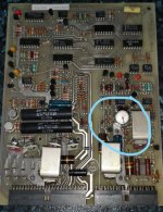
The first place I would recommend that you check is the bias and interface board. When I first started working on mine I noticed that the 82uF capacitor (the taller one with three leads) was kind of burnt looking and another capacitor was bulging. I replaced those and it got the system to turn on. The bias and interface board does generate the voltage for the fans. I think you are correct with the fan voltage, but I do know it is a weird square wave AC voltage that the fans require. That is generated by the bias and interface board so part of that board is working for sure if the fans are going. From what I understand, the bias and interface board is kind of like the "brains" of the power supply so that would be the first place I would check.
Another thing to double check is the load on the PSU. The main +5V rail needs a minimum of 6A for the PSU to function properly, although I would guess the voltage would be higher than 5 in that situation. Also be sure that the connections to the back plane are good. There is a sense signal that the PSU looks for, and not having that could make the PSU shut down.

The DC OK LED flashing indicates that a voltage is out of spec. The CIM card triggers the DC OK LED. The frustrating issue with this feature is that the DC OK LED will flash if any of the voltages are out of spec. A bad component on that board could cause the voltage checking function to work incorrectly. Although from what you describe I think the problem is not in the CIM.

The PSU has a couple of fail safe modes. It has a crowbar circuit for over voltage and a thermal shutdown if I remember correctly. I had it enter thermal shutdown once for running it outside of the case without fans. After letting it sit for a while, does it function normally again or does it still only power the fans? Is the airflow sufficient through the PSU?
 
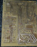
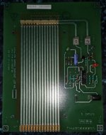
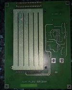
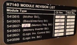
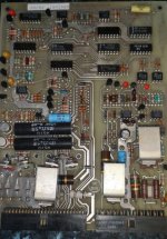
Thanks, I have read through the second post also. I had previously physically examined the caps in the PSU with particular attention to the Bias and I/F board as suggested and they appear ok. I will remove the caps from the board and test with a cap meter but I think I'll replace them anyway as there are not that many. My PSU also has an air flow sensor PCB next to the Bias and I/F PCB that I couldn't see in the schematics or on the PSU revision label, this has two test points on it. I've attached some photos.

C.jpgBias Front_LI.jpgBias rear.jpgAir flow front.jpgAir flow rear.jpg
 
The two caps you circled were the ones that I replaced. I didn't check any of the others on my board. I just might do that myself too, especially since it looks like there are some tantalum caps.

The air flow sensor was another board that puzzled me. The documentation I have doesn't show that board either. I have wondered how it works since there doesn't appear to be a way that it can sense that.
 
Found basic info info on air flow sensor PCB in schematics, looks like TP1 is +5V and TP2 is over temperature shutdown test point. should also be able to connect to J2 to check other voltages and signals.
Air flow sensor pin out.JPG
 
That's very helpful. So it appears that that card doesn't directly detect the air flow, but rather has a temperature sensor and monitors the fans.
 
I've not managed to find any info on the air flow sensor card, I've searched on all the numbers and names on the PCB. I've put an order in for the electrolytic capacitors on the bias and interface and air flow sensor PCB's from mouser. My capacitance meter only goes up to 600 uf so I've not been able to check the two huge can electrolytic capacitors on the right side of the PSU viewed from the rear. They are no bulging or leaking.
 
I think you are correct with the fan voltage, but I do know it is a weird square wave AC voltage that the fans require. That is generated by the bias and interface board so part of that board is working for sure if the fans are going.
35V 70Hz square wave drive only. It was a unique part created by Nidec/Torin for DEC and AFAIK there are no interchange parts for it.

From what I understand, the bias and interface board is kind of like the "brains" of the power supply so that would be the first place I would check.
Be careful - the 11/44 PSU stores something like 400VDC after the power is disconnected, and if there are PSU modules missing or the bleeder resistors or circuitry are damaged, it can take an extended period of time to decay to safe levels!
 
I've replaced the electrolytic capacitors on the Bias and Interface PCB and for good measure and considering it only had two electrolytic capacitors on the Air Flow Sensor PCB I have replaced them also. I tested the removed capacitors and all of them seemed to have a correct reading with my cap meter. I still only have the fans running with no other voltages present :(. No idea where to troubleshoot the PSU from here.

Recapped Bias and Inerface PCB.jpg
 
That's a shame that changing the capacitors didn't get any result.

Where are you checking the voltages? Directly on the output of the PSU, or in the computer itself? I have read that the flex cables can break at this website: http://retrocmp.com/pdp-11/pdp-1144/my-pdp-1144/power-supply

I hope this might help you in diagnosing the issue. I will go back and take a look at the documentation too and see if I can think of anything else.
 
I have an 11/24 it doesn't have the flex cables it has the standard DEC (Molex?) connectors. I have been measuring at the backplane. Reading the other posts, my 11/24 post and an 11/34 post I'm now a little concerned about the 82uF cap that I've used to replace the three legged cap.

RT07259 EEUFC1H820 Panasonic Capacitor 82Uf 50V

GGBOB69239-1.jpg
GGBOB69239-1.jpg

Product Description

The Panasonic FC series capacitors are automotive grade type A, radial leaded polarized aluminium electrolytic capacitors. The capacitance value ranges from 2.2µF to 15000µF. These capacitors are perfect solution for applications, which require ultra low ESR, very high ripple current and very long life in small mounting form.

Product Features
  1. High reliability
  2. Automotive grade AEC-Q200 compliant
  3. Rated voltage range of 6.3VDC to 100VDC
  4. Tolerance of ±20%
  5. Endurance of 1000h to 5000h at 105°C
  6. Operating temperature range -55°C to 105°C
Product Details
Capacitance:82µF
Capacitance Tolerance:± 20%
Capacitor Terminals:Radial Leaded
Diameter:8mm
ESR:-
Height:11.5mm
Lead Spacing:3.5mm
Lifetime @ Temperature:3000 hours @ 105°C
Operating Temperature Max:105°C
Operating Temperature Min:-55°C
Packaging:Each
 
These are complex PSUs. I spent some time withe H7144C and D in the VAX-11/750. Similar in many ways to the H7140. You can’t really fix them by random replacing of capacitors. There are plenty of interlocks in these which prevents them to work unless you know what you are doing. One has to figure them one step at a time , overriding any interlock that might interfere and measure what is going on.

I suggest that you read the manual very carefully and study the schematic at the same time. Identify each subsytem and verify that it works as it is supposed.

/Mattis
 
If I understand correctly there is 35V to the fans but nothing else, right?

That basically means that some major parts are actually working. The rectified 300V gets converted down to a proper 35V. 35V is chosen so that a set of backup batteries can cut in if there is a power outage and will then power everything which is off the memory regulator board.

So it is very likely that there are 35V in to the memory regulator board, but it will not run. Perhaps because of the MEM DC ON L signal on J1-3 ? Did you check that one?

If that is correct then there is some problem inside the Memory regulator board. In that case you could probably check this module with a stand alone PSU providing 35V into it. Asserting MEM DC ON L should enable 15 supply to all control logic on the board.

If the MEM DC ON L is not asserted then you need to check the BIAS AND INTERFACE BOARD. It comes from J2 H on this board. There is a bunch of TTL logic on this board that has to have the correct inputs to assert the MEM DC ON L. Check this board for proper operation. For example it tries to detect that we have 300V input. Is that signal asserted? It looks like it tries to check if the 12V BIAS voltage is correct. And the DC ON L has to be asserted.

/Mattis
 
Hi Mattis, I went for the cap replacement on the Bias and Interface board because I had seen a few posts on google and VCFED around C4 failure, there are only 4 electrolytic caps on this PCB so I decided to swap them all. sadly all of the removed caps tested ok with my cap meter but I've found in the past that they could behave differently in circuit. I'll go through your recommendations above on my PSU. I'm not overly confident working on switching PSU's especially with 300VDC present:nervous:.
 
The 300VDC is troublesome. When I worked on the H7144 PSUs for VAX-11/750 I used an insulation transformer in series with a variac. That gave some kind of safety. At least if I kept one hand in the pocket.

If you checked that the 300VDC sensing circuit is working correctly then you can probably override it and work with much lower voltage just for testing provided that the load is not to high.
 
Last edited:
And 12 V BIAS can be provided from a bench supply instead, making sure that all logic works fine anyway. Input on J2 B/2 pin.

Then you can work with the circuit without beeing afraid at least if you keep the variac output in the lower range.
 
To override 300 VDC sensing circuit just short circuit pin 3 of E7 on the BIAS AND INTERFACE BOARD to ground. If you then use a variac to ramp up the input AC then no harm can happen.
 
Back
Top