• Please review our updated Terms and Rules here

PDP 11/45, Part 2

Marty

Veteran Member
Joined
Jul 26, 2009
Messages
3,141
Location
Boulder , Colorado USA
Hi All;
I an starting a new thread for the PDP 11/45, a Continuation of the fun we had in part one.. Here is the link for the Start of the Old Posting -- http://www.vintage-computer.com/vcforum/showthread.php?40889-Pdp-11-45, And Here is the Last page for that thread -- http://www.vintage-computer.com/vcforum/showthread.php?40889-Pdp-11-45/page21 ..
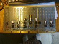
I have started to get back where I was supposed to be when I finished on Saturday, I found out that I had Inverted both the direction I was Counting, A thru V and side 1 and 2.. So, after getting that straightened out, and checking it on the PDP 11/45, I can now start doing bits 14 and Lower, checking every few bits to make sure I have them wired correctly..
020320141003.jpg

THANK YOU Marty
 
Last edited:
On the new thread - Ok - we here now.

On bus pin Reversal[SUP]3[/SUP] - Oh my... again? We need to find a way to get you past these issues. It simply can't continue if you are to make progress and avoid damage to your system(s).

Does anyone have any cribs or "practice" advice to help with this especially?

I am at a loss, and very concerned.
 
Aside from a lot of practice with a mirror and tie-tying (watch those hands!), consider L4 (Labels Lovingly Located, Liberally ...).

Find some wire of suitable diameter and thick insulation, extract wire, snip insulation to length and then slip over every A1 pin as a reminder of L/R and A/F? Alternatively, colored shrink-wrap tubing and locally-applied heat. Then practice counting (well, "lettering") in base 18 :->.

(In case you may need to wire-wrap later, pick a power-pin for your reference. If you need to play with the wire-wrap on that you're in really deep trouble ...)

???
 
Hi All;
That is why I do only a little and then Test it, especially when first starting on a DEC Board.. I think part of the problem or confusion was because I had Originally wired my Maintenance Board, from the other side.. And I think Maybe part of the problem, is I am used to Reading in the other direction.. And ever since I was a small kid, I had trouble with Left and Right, I am mostly over it, but sometime it still haunts me.. And on the side pins 1 against pins 2, it is mostly difference between how this board was laid out against the previous Board, which side was on top and which side was on the bottom of the plane..
There was NO damage to the Machine..
I am down to bit 10, having worked my way from bit 17.. Its going alot faster Now.. I have bits 10 to 6 done.. I had a small problem (I think) a small wire was shorting bits 6 and 7 together and was causing bit 7 to act funny, it would not turn on, but switch 6 would turn on bits 6 and 7.. All is well now.. Now to bits 5 down to 00, left to do..
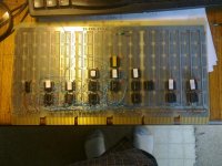
Here is a picture of it so far..

020320141003.jpg

THANK YOU Marty
 
Last edited:
Hi All;
I have Finished wiring up the SJB Board, and when I plug it in there is NO Smoke !!!
I have tried to Deposit 101 to 177566 and No go, as well as 777566 and that was worse..
So I need to find out Why it doesn't like 177560 and above.. first is to check the switch settings on the M7856..
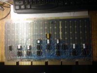
And Here is a picture of the Done Board..

020320141004.jpg

THANK YOU Marty
 
Hi All;
Its still Running Self Modifying Code.. So, I definitely need to look into the Register Thing.. And try to find out how to make sure that they work, and that, that is Not where the problem is, Even thought I suspect that it is.. At least I can use my 16K of Memory with out worrying about Memory Management.. I did check the Switch settings on the M7856 and they were/are correct, but I did change the Baud rate so I could see it better down to 110 Baud..
THANK YOU Marty
 
Hi All;
I have found that the Front Panel and the Cable are OK.. Following it to the next step, The 74S04's on the PDR Board are also good.. The input to the 74S153's is the Output from some 74S174's and the 74S174's don't seem to have a Clock, which needs investigation.. The clock I think comes from the TMC Board..
THANK YOU Marty
 
Hi All;
I MAY have found Something, a 7425/8815 May be bad.. I am going to replace it and see if that makes any difference.. I can get its inputs to go from High to Low, when pressing different switches, but the OutPut Always stays Low..
THANK YOU Marty
 
Hi All;
Well, I replaced that IC, I do not know If it helped or not.. With the Switches it does the same thing.. But tracing out this circuit, I did find out about addresses 0777770 and 0777570, I can read those addresses with out any address error light coming on.. I got it to accept a Deposit at address 0777566, but NOT at 1777566, it seems that bit 15 makes a difference on whether I can Deposit a 101 to it..
THANK YOU Marty
 
Hi All;
Well, I got a program to Run, without any Address Error Light lighting up.. Its a variation of the one given by Roe --

000000 load address
012737 deposit
000101 deposit
177566 deposit
000000 deposit
000000 load address
Halt switch up
Start
Only I changed the last memory location from 000000 to 000774.. (I think that is correct) Please tell me IF it is WRONG and that I need another number like 000773 or 000776.. I want it to repeat itself.. But it is Running, still NO "A" on the screen..
Should run and display an A. And it IS NOT self Modifying, I have run it for along time and went back and checked the Core and it has not changed..
THANK YOU Marty
 
Hi All;
I got it to accept a Deposit at address 0777566, but NOT at 1777566, it seems that bit 15 makes a difference on whether I can Deposit a 101 to it..

Hi Marty,

I have been following your efforts for a long time now. Congratulations on all that you have accomplished!

6 octal digits (777566) represent a valid 18 bit address (3 bits per digit x 6 digits = 18 bits).
When you go to 1777566, you now have a 19 bit address - that is maybe why the machine is complaining?

I am definitely not an expert, but I have been caught by my own incorrect thoughts on addresses with in my PDP-11/23, so I thought I'd put in my thoughts.

I wish you continued good luck!
smp
 
Hi All;
Thank You, SMP for Your Response, I think I now know where my problem is/was, I put an Extra 7 in the Address.. I had been trying to output to 1777566 and not at 177566, I need to try that address and see if it makes any difference in the program..
THANK YOU Marty
 
Hi All;
I had been trying to output to 1777566 and not at 177566, I need to try that address and see if it makes any difference in the program..

OK... I have had this problem before, and RSX11M+ helped me out significantly. Please see this thread:

http://www.vintage-computer.com/vcforum/showthread.php?39285-Interface-to-TU58EM

In there, I was using ODT built in to my PDP-11/23, which is quite different from you with your front panel, BUT RSX11M+ pointed out that I was trying to do output to 177506 when I should have been trying to output to 777506.

I do not know if this will be the same issue for you, too, but I could not help but try and let you know.

Hopefully, RSX11M+ will see this and jump in, too.

smp
 
Last edited:
Hi All;
Well, I replaced that IC, I do not know If it helped or not.. With the Switches it does the same thing.. But tracing out this circuit, I did find out about addresses 0777770 and 0777570, I can read those addresses with out any address error light coming on.. I got it to accept a Deposit at address 0777566, but NOT at 1777566, it seems that bit 15 makes a difference on whether I can Deposit a 101 to it..
THANK YOU Marty
I am very confused.

777770 is a CPU internal register - Program Break register.
When you say 1777566 I'm not sure if you mean 177566 or 777566.

Can you help me out here?
 
So I see there have been posts between my last visit and my attempt to help.

Marty - I've seen this misunderstanding coming for a while without quite knowing how to go about it with you. SMP correctly identifies it - but I'm afraid the assistance to him in the thread he links might not quite catch on with you because you're not using a machine with MicroODT - yours has a binary Switch Register Console.

At the risk of being a little wordy - I need to tackle two issues.

The first is that you have 18 address switches representing address bits 0-17 (or better 17-0). This is capable of inputting any address from 000000 to 777777. However, this brings us the the second issue... the CPU executing a program can't manipulate bits 17 and 16 of the address under direct program control.

The MMU handles this by "Remapping" CPU addresses in the high 4KW of it's range to the high 4KW of "Physical" memory. In other words - it adds the two upper bits.

This happens automatically without you having to do anything. The MMU is setup to do this by a hardware reset. The mapping can be changed under program control, but need not be to get started.

So, the programs you input that access 177560 for example, are re-mapped by the MMU to 777560. However, when you wish to access the Console SLU board from the Switch Register - you must input the PHYSICAL address of the board - which includes bits 17 and 16 - 777560.

I know that's a lot to swallow in one go, but it's a concept you need in order to proceed - and have been tripping over on and off for a while.
 
I must also add that this is further complicated on your machine in particular - because the Address and Data areas of your Console have various options set by the rotary selector switches - which I asked the settings of in a previous post.
 
Hi All;
Yes, RSX11M, I have made some progress since you were most likely here..
First, Since I am NOT using the Memory Mapping option, as that was WHY I Wire-wrapped the SJB Board, to simplify matters..
Next, I was looking at the Addresses 777770 on the TMC Board as I was trying to find the Problem with the Display Register, and this is the area of the Schematic that it goes to.. the 777770 goes thru a Mux, as well as 777570 and is part of the Output for the Display Register.. I gave up on that for Now, and for Now it isn't going to work..
I have since tried to make the M7856 work, with out giving me an Addrs Error led.. And it was during this and after Re-Reading the Manual for the M7856, and SMP's postings, that I found I had too many 7's in my address, which was why the system gave me an Adrs Err.
So I have spent most of the day researching this out, which Is OK, as I did get the program to RUN with NO ADRS ERR Led going ON.. I think I have tried both 777566 and 177566 and they Both work..
Currently I have an Output on the 2017 Comm IC. I do not have it at the Boards Output nor on the input to the 1488, so the problem is somewhere between there.. I don't know exactly what it is outputting at this point, but I am Glad it is outputting Anything.. I am going to work my way One gate at a time till I get to the 1488.. I just found I had miscounted pins on the uart chip, so I am not serially outputting yet, I will look at the rest of the pins on that IC.. I was looking at pin 26 instead of pin 25, and pin 26 is an address pin, which is working nicely..
Re-read posting #12, and it may explain my confusion, I was interpreting the numbers that I was given as longer than they should or needed to be..
THANK YOU Marty
 
Last edited:
If it's true that you've been operating without the MMU plugged in, then please ignore my advice and the above ramblings. They're of no use to you whatsoever.
 
Hi All;
RSX11M, I WILL NEVER IGNORE YOUR POSTINGS !!!! I had only recently changed over from the Memory Management Boards to the SJB Board, only to make it simpler for me to work my way thru.. But, eventually I plan on going back to the MMU Boards, so I can have more memory.. But, for Basic Bringing it up, then MMU is not needed..
One of the places of confusion was my M9312 Board and the manual for it stated that it's Rom/Prom address was 165020, the system cannot handle that address, now maybe 65020, but not 165020.. It gets an Adrs Err at that address every time..
Before I left for an appointment tonight, I was scoping the Uart Ic, and I found both clocks working, and was in the process of going around the chip checking all of the connections, for something that might look bad.. I MAY have found something, but until I go the rest of the way around I will not know, and even then from that or those pins that I don't like I need to work my way back to either make it correct or not correct..

""because the Address and Data areas of your Console have various options set by the rotary selector switches - which I asked the settings of in a previous post. "" I had told you in a previous posting that I had my Front Panel set on "CONS PHY" and "DATA PATHS" But, I assume it got missed..

Bipolar Disorder is what I thing my computer is suffering from, Would a lobotomy do any good ??
THANK YOU Marty
 
Last edited:
We have to simplify this entire issue about the console output. Until you can reliably do the following, nothing else matters:

Run/halt switch in the down(halt) position
Toggle START. This will reset the computer.
Set switches for 777566
Toggle LOAD ADDRESS
Set switches for 000101
Toggle DEPOSIT (upwards)

You MUST see an A on the terminal/whatever connected to the dl11w. If you don't, stop here and fix it. It may have something to do with the rotary front panel switches, or your dl11 cable, or your rs232 connection into the PC or you may need a null modem cable, but please do not try to proceed further until this works.
 
Back
Top