• Please review our updated Terms and Rules here

PDP 11/45, Part 4

Hi All;

Dave, Thanks for the Information and Links for Unix 6..
On a side Note I have copied Unix 1 thru Unix 4 and have to do Unix 5 thru Unix 7..
If nothing else, I can see the Evolution of the Unix and "C" toward what is more like what we have now..

I know I will be needing this Information, if I am ever going to get it Running under either SIMH or my Real Machine..

I think, my main fear is getting SIMH going and Running, since I use it very Little and so I am Afraid to go and use it..
I know that this Sounds incredibility ridiculous..
But, that is the main Reason I have stayed with trying to do it on my Real Machine first and then after some trouble or problem will I either ask people or try it on SIMH..
I have written down How to do things with SIMH somewhere, but, I always loose the notes, by the next time I need them..

"" I managed to pick up some mains cable today of the correct type (hooray)... ""
IS this the Cables that You have had made or is this some other Cables that You found or otherwise acquired ??

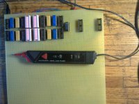
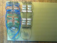
I have also wired up 1/ 12th of the new revised MACT unit for testing the various boards..
001.jpg 002.jpg

Now it's 1 / 6th of the way there..


THANK YOU Marty
 
Last edited:
Hi All;

Pbirkel, see post # 353..

Dave, I Just had a chance to look at Your References for Unix the 6th edition..
And they are All very good, So maybe I won't have as much trouble as I thought with SIMH..
My only objection is that they are for the PDP 11/40 and NOT the PDP 11/45.. Hopefully, we can work around this..
Bill should have a Hayday since these are set up for His 11/40, Another possibility for Him would be XINU or an earlier Unix Edition, like 3 or 4 which takes less Memory.. But, these still need about 26K of memory or so, So maybe not if Bill only has about 16K of memory..

THANK YOU Marty
 
Last edited:
Hi Marty,

I've been working a little bit more today on the halt I get on my machine in CKBME0 (traps diagnostic). It looks like its a race in the code as written with transmit double-buffering on the DL11. Does CKBME0 pass on your 11/45? If so, could you tell me how your DL11 is configured (baud, stop bits?)

thanks much,
--FritzM.

Update: this is verified -- reconfigured the DL11 to 1200 baud and the diagnostic now passes 100%. Worth noting when trying to get these older diagnostics working... I will write up my findings in more detail in a blog post later today.
 
Last edited:
Marty,

The run.conf from here "http://www.in-ulm.de/~mascheck/various/ancient/v6.html" is for an 11/45:

set cpu 11/45
att rk0 unix0_v6_rk.dsk
att rk1 unix1_v6_rk.dsk
att rk2 unix2_v6_rk.dsk
att rk3 unix3_v6_rk.dsk
boot rk0

Just copy this file + the required RK05 disks into a directory and run SIMH as shown at "http://www.in-ulm.de/~mascheck/various/ancient/v6.html". It runs... No 'getting around' required...

Dave
 
Hi All;

PBirkel, "" Don doesn't really mean anything other than the standard acronym, it would seem. ""

Well. Yes and No.. DEC did Really have multiple Testing Units, which was probably Called an ACT, that were used for Testing whole machine and Individual Boards.. I could use the Schematic for one of those, which most likely Doesn't Exist.. They are also Reference in the book, " DEC ENGINEERING"" By Bell, and Mudge and McNamara.. Page 88..

"" I guess that I shouldn't inquire as to the actual (in the real-schematic sense) basis for your MACT? ""

In the Real sense, the Schematic is very simple, it's the Wiring that is Hard.. And the Basis for this Is that I have two GRA Boards that are Acting up, in other words not working, I have two Data Path Boards that need to be checked, one Definitely Does Not work.. And about Four IR Boards that do Not work, All of which need to be fixed.. And One or Both of the Memory Management Boards that need fixing.. I would think that this is enough of a Basis for Building my Own MACT Board..
And In time I am thinking of trying to build and Design come kind of an actual ACT Board(s) or System that would Test a Board, but this would be a ways off.. But, the thought is there anyway..

Fritzm, Which DL-11 Board are You running ?? An M7800 or an M7856 ..
The M7856 has two Jumper settings that are Not really Documented.. Switch 4 Positions 1 and 7 MUST be ON..

"" I've been working a little bit more today on the halt I get on my machine in CKBME0 (traps diagnostic). It looks like its a race in the code as written with transmit double-buffering on the DL11. Does CKBME0 pass on your 11/45? ""
Yes, it Does Pass..
"" If so, could you tell me how your DL11 is configured (baud, stop bits?) ""
Mine is set at 9600 Baud, 2 Stops Bits and 8 Bits word size..

Dave, Thank You for the Update and the Information.. I will Look into thing more fully Tomorrow..

THANK YOU Marty
 
Hi Marty,

Which DL-11 Board are You running ?? An M7800 or an M7856 ..

I am running an M7800, at 9600,N,8,1. The test failure on my machine is definitely correlated with serial timing, and I can see the bug in the diagnostic code as written. I wonder if its really close enough that the extra stop bit makes a difference?! I'll try rejumpering my card for 2 stop bits later today and see...

thanks,
--FritzM.
 
Hi All;

PBirkel, "" Don doesn't really mean anything other than the standard acronym, it would seem. ""

Well. Yes and No.. DEC did Really have multiple Testing Units, which was probably Called an ACT, that were used for Testing whole machine and Individual Boards.. I could use the Schematic for one of those, which most likely Doesn't Exist.. They are also Reference in the book, " DEC ENGINEERING"" By Bell, and Mudge and McNamara.. Page 88..

THANK YOU Marty

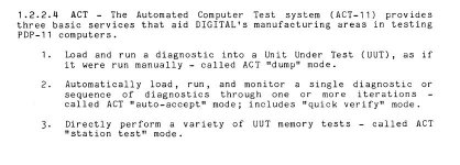
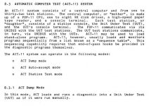
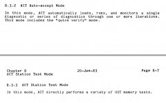
Basically correct; I was referring to the specific code sequence: JSR PC,(R0) back to a monitor (where R0=contents(42)), and the use of locations 42/46/52, to return back to a monitor (XXDP+ in diagnostic chain mode) as well as what DEC manufacturing used in their ACT-11 (automated computer testing) system.

From the DEC diagnostic design guide on bitsavers:

Capture1.JPG
Capture2.jpg
Capture3.JPG

Basically the control system was (in my experience) an 11/34 with several RK05 drives, and a custom UNIBUS switch. Each port on the switch connected to a UUT system via UNIBUS, so the ACT system would essentially DMA diagnostic images into the memory of the UUT, launch them, and then monitor them for pass/fail. For each type of UUT system a preconfigured script of the diagnostics to run was provided on the ACT-11 system. Basically the operator would plug a board into the UUT, power it up, and enable the tests to start, which would run unattended, producing a pass/fail report at the end. Pass means ship the system, fail means back to debug station.

When I was at DEC in the late 70s I was with the PDP-11 diagnostic group and went down to the DEC manufacturing site for the 11/60 in Aguadilla, PR where I helped integrate the 11/60 diagnostic test process into their ACT-11 system.

I think what Marty is doing is a bit different, developing a test jig to allow direct control/observation of all the I/O pins on the card edge connector to facilitate benchtop testing.

Don
 
Last edited:
Hi All;

Fritzm, "" I'll try rejumpering my card for 2 stop bits later today and see... ""
My Mistake, I had One Stop Bit, But, Yes, go ahead and try two, it might make some difference..
Also, as You did and as You saw slowing down the TTY speed made the problem go away..
Since at that time using a TTY actual Teletype would have been at 110 Baud and some other Terminals to as fast a 300 Baud you would still have plenty of time for things to settle down in the code..

Don, Thank You for the clarification.. "" Basically correct; I was referring to the specific code sequence: JSR PC,(R0) back to a monitor (where R0=contents(42)), and the use of locations 42/46/52, to return back to a monitor (XXDP+ in diagnostic chain mode) as well as what DEC manufacturing used in their ACT-11 (automated computer testing) system. ""
Yes, I knew this, (but other may not have known this) from my reading and typing in of the code..

"" Basically the control system was (in my experience) an 11/34 with several RK05 drives, and a custom UNIBUS switch. Each port on the switch connected to a UUT system via UNIBUS, so the ACT system would essentially DMA diagnostic images into the memory of the UUT, launch them, and then monitor them for pass/fail. For each type of UUT system as script of the diagnostics to run was provided on the ACT-11 system. ""
This Part I would love to know more about this.. Especially about a UUT..

"" I think what Marty is doing is a bit different, developing a test jig to allow direct control/observation of all the I/O pins on the card edge connector to facilitate benchtop testing. ""

YES !!! Exactly !! Thank You Don.. Even if I Automate this it would still be based on control and observation of I/O pins..

THANK YOU Marty
 
Last edited:
Hi All;

Thank You, Don for clearing this up for me..
I should have guessed as to what it stood for, but, the way I read it at first, was that it was a special Card or group of Cards that used the UniBus in a special way to test multiple units.. "" and a custom UNIBUS switch. ""

THANK YOU Marty
 
Don: Thanks for the explanation regarding the ACT-11.

It sounds then like the "UUT system" was a full PDP-11 system of some type (else how can there be a "UUT system console"?) into which one plugged the actual UUT module? So in Marty's case the "UUT system" would be an 11/45 and one was doing module-swapping?

Then ACT-11 was a fast centralized system to load/initialize a set of "UUT systems" with XXDP diagnostics. Have I got that right?

-----
paul

ACT-11 was for system testing, not module testing. The central ACT-11 CPU (like an 11/34) had several local disks (like RK05's) that contained all the diagnostic image .BIN files. The ACT-11 monitor would download diagnostics to the target system via direct DMA thru the UNIBUS, run them, and then monitor the pass/fail result thru the in-memory mail box data structure.

There was a board/cable that plugged into the UUT backplane that basically was all the UNIBUS signals, plus some out of band control signals like INIT, AC LO, DC LO, etc that allowed the ACT-11 system to remote boot the diagnostics.

I am familiar with ACT-11 testing racks and racks of PDP-11/60 CPU boxes and local memory. No local storage or other peripherals involved.
 
Hi All;

Don and PBirkel Thank You for clearing things up..

I didn't know the difference between System Testing and Module Testing, I thought they were kind of the same..
Since, Failing different Tests would point to different Modules as having failed..

"" I was being mislead by Marty's focus on module-level testing. ""

I didn't know I was Misleading anyone, Sorry about that..

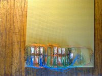
I am now working on the next 1 / 6th of my MACT Tester..

001.jpg

When this is wired up that should be 1 / 3 of what I need to complete this Tester..


THANK YOU Marty
 
Last edited:
Back
Top