• Please review our updated Terms and Rules here

Pdp 11/45

Marty

Veteran Member
Joined
Jul 26, 2009
Messages
3,141
Location
Boulder , Colorado USA
Hi All;
I am going to put away the 11/40 and I am going to try and see what condition the PDP 11/45 is really in.. (see I'm Back, PDP11/40..) For details..
It need to have a "Wooden Frame" built for it Just like the 11/40.. And I need to straighten alot of the Pins on the BackPlane/MotherBoard, before doing anything else.. I will use my PC Power Supply that I used for the 11/40, on the 11/45.. And with the Maintance Module, and the Other Wire-Wrap Boards I built, maybe I can Ascertain what condition the PDP 11/45 is in..
THANK YOU Marty
 
Man, don’t you have any easy projects you can work on?, something like a nice simple Qbus system like an 11\23 or something that’s easy to get going.
 
Hi All;
QBus, I Don't consider QBus simple, But to answer Your Question.. NO !! But, THANK YOU for Your Caring and Concern..
Almost everything Computer or Electronic, I have Doesn't Work, Otherwise I couldn't Afford it.. Getting something in Working condition, is WAY above my budget.. I have a number of Old Radio's and OLD, OLD TV's and they all have something Wrong with them.. I think the ONLY Old Computer that I have that works is my Altair 8800, and even the Two Disk Drives in it Don't Work, they used to work, but since a year or two ago they don't anymore..
None of my PDP's work.. Which gives me something to keep me out of Trouble, Or so I'm told..
THANK YOU Marty
 
Hi All;
I think I got All of the Pins straightened out on the MotherBoard.. I have some running around to do today, So, it will be much later, before I can continue and start building some kind of a Mounting system for it..
The Front Panel on the 11/45 is much better than the 11/40, even though the /45 is missing the knob.. (It may be around here somewhere..) And I don't have the Power key to it either, which I didn't have for the /40 either..
THANK YOU Marty
 
Hi All;
I have re-down loaded the files for the PDP 11/45 from Bit Savers, I have not had a chance to either look at them nor print them out..
I have the original Long Black Snake of a Power Cord for it.. The Front Panel is missing all of its Bulbs..
THANK YOU Marty
 
Hi All;
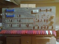
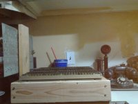
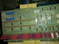
Here are some pictures, for those of You waiting for me to take some.. I have Not mounted the Front Bezel, as I need to figure out the length of the spacers, and of course there is no Power Supply attached as of yet..

01092014929.jpg 01092014931.jpg 01092014932.jpg

THANK YOU Marty
 
Hi All;
I went thru most of my Boards and I put them in the Backplane, mainly to see If I have all of the Boards.. I have M8100 thru M8109, and I have put in One Semiconductor memory Board.. I am not sure that I need an M8110, and I am not sure If I have one.. I have to re-check thru my Core Memory Boards, to see what numbers I have..
They will All have to come out and I will need to make a through check of Voltages and Ground wires.. Both with an Ohm meter at first, with only one Board in at a time and then with voltages, on the proper wires.. Before the Boards go back in..
and Last but not least I have to get the Led's working on the Front Panel, as well..
THANK YOU Marty
 
Hi All;
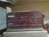
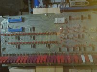
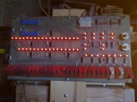
I have put Leds in all of the Bulb Sockets on the Front Panel and I have checked that ALL of the Leds work.. Here are some pictures..

01102014934.jpg 01102014936.jpg

THANK YOU Marty
 
If memory serves me, the unlabeled white key-switch next to the "0" is a lamp test.

I bet you knew that already?
 
Hi All;
RSX11M+, No I didn't, so Now I have to figure how to make it work.. But just guessing, if I have my connections correct they should All light up, when switched.. Is it thru the Diodes that are all over the place ??
THANK YOU RSX11M+ !!! See Picture..

01102014937.jpg

THANK YOU Marty
 
Last edited:
Hi All;
I have "Ohmed" out the Red Wires for +5 Volts to the Various slots.. Slots 1,6-9 on two wires.. Slots 2-5 on two wires.. Slots 10-15 on two wires.. Slots 16-25 on eight wires.. Slot 26 one wire.. Slots 27-28 two wires..
Now to check all of the Black "Ground" wires..
It looks like ALL of the Ground wires are all tied together.. For Now I am not going to worry about all the other voltages, until I need any of them.. Such as -5, -12, +12 and possibly +20.. Then what is left is AC LO and DC LO, which eventually I need to find..
THANK YOU Marty
 
Last edited:
Hi All;
RSX11M+, No I didn't, so Now I have to figure how to make it work.. But just guessing, if I have my connections correct they should All light up, when switched.. Is it thru the Diodes that are all over the place ??
THANK YOU RSX11M+ !!! See Picture..

View attachment 16774

THANK YOU Marty

LOL - Ummm... I think that key your finger is on is the Register Deposit key. I guess it's performing that way because the rest of the system isn't connected.

It appears one of the three normally white keys has been replaced with a red one. I think the one you want is 12th from the right. (immediately to the right of the last group of 3 dark ones)

Just thought you should know since I'm sure you'll want the function again once it's all hooked up.
 
Hi All;
RSX11M, I am not sure which picture You are referring to "that my finger is on" But You are Right as far as which switch works all of the Leds..
Since I have not seen a "good" picture of an 11/45 front panel, not only has the white key been replaced, but the Switch (May be) mounted in the wrong way.. As the switch is "up" to turn on All of the Leds, and Down to turn then off, and I would think that it should be the other way around.. But, I am NOT going to make a mess and try to ""FIX"" it, I might break it far worse.. So, I will just leave it alone..
I hope to try tomorrow to connect the appropriate ground wires, and most of the +5 volt wires to the Power Supply, when I am tired, I will not try to do something that might effect the whole system, it can wait.. Then I can see if anything remotely works..
THANK YOU Marty
 
...But You are Right as far as which switch works all of the Leds..
Since I have not seen a "good" picture of an 11/45 front panel, not only has the white key been replaced, but the Switch (May be) mounted in the wrong way.. As the switch is "up" to turn on All of the Leds, and Down to turn then off, and I would think that it should be the other way around...

Actually - it's mounted correctly ("Up" to test?) and once again my recollection is that it's a momentary - let go and it will spring back to the "operate" position.

Anyway - that's my big contribution today. :geek:
 
HI All;
Thank You to all for the correct information.. I think that, that switch is one of a number of switches that has been replaced, and so it is not momentary as it should be, as well as being the wrong color, Red instead of White..
THANK YOU Marty
 
Hi All;
I have Wired in +5 and Ground.. I now have Leds that light and stay on, because of the Drivers (7416's or something like that) that since there is no signal from the Boards their inputs are High and so the Leds turn ON..
Which means that at least the Front Panel has juice to the Ic's and seems to be OK.. No Smoke..
So next is putting in the boards and see what happens ?!?!
THANK YOU Marty
 
Hi All;
It is Not working, But it is NOT Smoking either..
With the the upper rotary switch set on User 1, and I have no idea if this is the correct place for the switch to be.. And the lower rotary switch set on Data Paths, then all of the Data and Address Leds light.. When the switch is on Display Register, then just the Address Leds are on and the Data Leds are Off.. And the RUN led is on, as well as the USER Led and the DATA Led is on..
There is NO memory board in the machine..
(EDIT) I just saw that slot 26 has the potential for putting the M7891 Memory board there with wiring in the additional voltages, Ithink just +12 Volts for that slot Only..
CAN I put an M7891 in Slot 17 where it calls for an M8111 along with an M8110 in slot 16, which I do not have (M8110).. Or do I need to put in a DD 11 MotherBoard for the Memory Board ??
Also, there is No Bootstrap/terminators, nor terminators in the machine.. I found an M930 terminator, and I think I have another one, just need to find it.. Will an M9302 Work for the Terminator on UniBus B ??
THANK YOU Marty
 
Last edited:
Hi All;
I have put in the two Terminators, and the M7891 in slot 26..
I have hooked up the +12 line and so far so good..
But, before I hook up the -12 volt line, when looking for the correct wire, my meter beeped between +5 and -12 Volts, and NOT wanting to make a mistake like "what affected the PDP 11/40" I wanted to KNOW what is the Correct Resistance between +5 and the -12 volt lines ?? My meter reads about 2.5 OHMS, Is that correct OR should I Pull all the Boards, which I might do anyway and Remeasure, Just in case their might be a short, between the two Lines.. I think I will Pull All of the Boards and Remeasure, Just to be sure..
THANK YOU Marty
 
Hi All;
I Pulled ALL of the Boards, as well as pulled the Power Connector for the Front Panel.. There should be no Connection as Far as I would think..
But it shows 49.7 Ohms, NOT infinity !!!!
AM I missing something ??
THANK YOU Marty
 
Back
Top