• Please review our updated Terms and Rules here

PDP-11 Diode ROM

Very nice. I had been thinking about making a diode ROM someday, wanting to see if I could make the whole matrix out of pluggable LEDs. I see this one is all jumpers, with only single rows of LEDs.
 
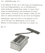
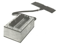
Sadly not from a PDP-11 - but this was how a Triumph Adler TA10 accounting machine was programmed in the 1970s, if you didn't have the later 1702 EPROM board and programmer:

Programmers produced "program sheets" and a lucky engineer got to solder/move diodes with pre-formed wires accordingly - and hoping they did not "just insert" an instruction...
 
...this was how a Triumph Adler TA10 accounting machine was programmed in the 1970s, if you didn't have the later 1702 EPROM board and programmer...

That's kind of hilarious, because the initial post inspired me to start noting down some ideas for a diode ROM board for microprocessors SBCs (it's been in the back of my mind for ages), and a '154 is exactly one of the things I was looking at for this. (Though I think I'll go with an LS154, even though I have some ancient HD74159P kicking around as well—turns out old NEC PC-8801 keyboards use those, and they break.)
 
That's kind of hilarious, because the initial post inspired me to start noting down some ideas for a diode ROM board for microprocessors SBCs (it's been in the back of my mind for ages), and a '154 is exactly one of the things I was looking at for this. (Though I think I'll go with an LS154, even though I have some ancient HD74159P kicking around as well—turns out old NEC PC-8801 keyboards use those, and they break.)
You may find it better to use 74LS138 3 to 8 line decoders, they have multiple enable inputs so they are easy to cascade with little extra logic apart from the odd inverter and usually much cheaper too...

More decoupling caps than on the boards on the photos would be a good idea as well!
 
You may find it better to use 74LS138 3 to 8 line decoders, they have multiple enable inputs so they are easy to cascade with little extra logic apart from the odd inverter and usually much cheaper too...
Yeah, I also sketched out some ideas about using those in my notes. I'm not a big fan of cascading logic in address decoding circuits if I can avoid it, though, especially demuxers like the '138 which are particularly slow. (The extra enable input of the '138 does help a bit with avoiding extra inverters, though.)
 
Yeah, I also sketched out some ideas about using those in my notes. I'm not a big fan of cascading logic in address decoding circuits if I can avoid it, though, especially demuxers like the '138 which are particularly slow. (The extra enable input of the '138 does help a bit with avoiding extra inverters, though.)
On the BM792, DEC used the 74138 instead of '154. Perhaps its easier to make a PCB layout with the smaller '138s?
 
FYI, here the schematics:
 

Attachments

  • m792base-schematic.pdf
    1.2 MB · Views: 10
  • q792base-schematic.pdf
    1.2 MB · Views: 4
  • m792bits-schematic.pdf
    3.1 MB · Views: 9
  • Like
Reactions: cjs
Last edited:
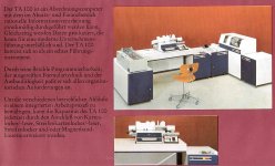
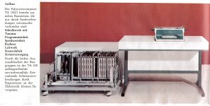
The TA 10 (TTL accounting computer) has a predecessor - the TA 100 which is transistor based.
It has much bigger (diode matrix) software...:

Computer with all peripheric accessories:
TA100_1_ALL.jpg

CPU (left) with console (right)

TA100_2_CPU.jpg

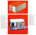
exchangeable software packs
These are inserted into front slots (bottom picture)
TA100_3_ROM.jpg

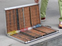
Opened program(s)
TA100_4_ROM.jpg
 
Back
Top