• Please review our updated Terms and Rules here

PDP-8 core memory troubleshooting

Looking at the schematics for the H212 (MM8-EJ) I see that EMA2 appears on drawing sheet 3 and is coupled to E14 pin 9 via wire link W1.

EMA2 should select between the upper and lower 4K banks.

I am just thinking out aloud here...

If W1 is removed - could we strap E14 pin 9 to ground or a convenient VCC pull-up resistor to make it a HIGH 4K or LOW 4K card - with the operational 4K appearing in the low addresses?

This might overcome the initial problems whilst we work on a full rectification for the other 4K half. Reversal should then be simple enough?

You really need to fix the problem in some way or another - otherwise you will be stuck running your own programs (as real-world programs - e.g. the assembler and compilers) will use this memory area and crash.

EDIT: Doesn't E11/9 connect to E10/3 and E10/4 connect to E11/10? This then goes off to the core stack on XPRD3? With E10 being an IC transformer and E11 being a transistor array? Or am I on the wrong schematic?

Dave

Thanks Dave,

Yes the MM8-EJ board kit could be modified to turn it into a 4K kit but fortunately the owner of the Lab-8/E found a H212 board so I am up and running (see my previous reply to Kevin).

As to your "EDIT:" I think you are looking at the wrong schematic. There are no transistors arrays or transformers on the H212 board. The H212 board schematics are just a bunch of diode arrays. It is on page 15 of the "MM8-EJ_Engineering_Drawings_May_73.pdf" from Bitsavers in the "pdp8e" directory.

Here is a picture with the open-circuit core wires pads highlighted:
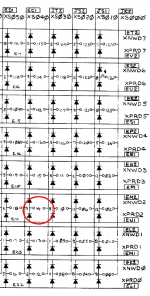
Core error.png

Thanks and best regards
Tom Hunter
 
Just as a different comment. I do know that I've read about people repairing the actual core mat as well. So it's possible, even if not the must fun thing.

Hmmm - the cores and the wires are microscopic. There may be some original jigs which were used to manufacture these cores and maybe these could be revivied to fix the core mat.
Really I think this was the very end phase and pinaccle of the core memory technology. It was extremely advanced technology to be able to compete against the emerging silicon memory.
I can imagine fixing a CDC 6000 series core which is relatively coarse, but not the H212.
The core used on the H212 is barely visible through magnifying googles with both lenses engaged AND a magnifying lamp. The wire is thinner than human hair.
You would need a good microscope and precision actuators to move around with your wire feed tool.

I am really curious - have you got a link to this "core mat repair" article?

Thanks and best regards
Tom Hunter

Not an article, but a recollection of a post, I think.

I wonder if it might have been Mattis Lind (who I think is also looking at this thread) who did it? Or maybe he remember who it was? For some reason my brain keeps saying Mattis to me... If not, then I'll to go searching around.

But yes, any such repair will require steady hands, a magnifier, patience and a good eye. But it would be pretty much about retreading a wire. Might also be tricky to find a replacement wire. Another broken core memory would be a good source, I guess...
 
Core repair/
I don't quite get the same magnification as your amazing photo (what did you use to make that?), but the broken wire is not obvious.

The photos are from a cheap "digital microscope" bought via Amazon (similar items available on eBay).

The cores on the H-212 are very tiny and tightly packed together compared to older core memory examples (things get smaller and denser over time) - see photo below!

I imagine it would be really very hard to repair/rethread the H-212 at the cores; but if one of the wires was broken outside of the mat then that might, just, be practical to repair with care, a steady hand and magnification.

An older ferrite memory core on the H-212 "mat" (the diameter of the larger core is approximately 1 mm):
h212coresversus.jpg
 
Thanks, I was looking at the schematic for the X-Y driver...

One possibility to think about would be an ac signal generator coupled to the faulty line by a low-valued capacitor. This should producing an ac voltage field around the cable that should reduce significantly after the break. A sensor (small coil of wire) connected to an oscilloscope should act as a detector.

By using this on both ends of the faulty cable should pinpoint an approximate location for the break. That is, if it works!

This would be performed with the power OFF and the core module on the bench.

Dave
 
I only know of two recent core repairs. The first is the 8/L that Anders repaired a X-wire on (https://pdp-9.net/pdp-8-l) the other is the straight-8 in New Zeeland linked above that Brendan repaired.

My PDP-8 core memory is still on the to do list.

The core memory Of Brendans straight-8 is of later design than mine, a bit like the 8/L. And as far as I recall he had a faulty X or Y wire. Mine has faulty sense wire.


H212 core is considerable is much denser than 8/L and straight-8. Much harder to work on in my opinion.

Ah. It was Anders repair that I was thinking of then. Thanks for clarifying.

And yes, this is definitely harder. But I wanted to at least make people aware that similar problems have been fixed. So it's not absolutely impossible. It's easy to otherwise just think that if it's in the core matrix itself nothing can be done.
 
Core repair/

The photos are from a cheap "digital microscope" bought via Amazon (similar items available on eBay).

The cores on the H-212 are very tiny and tightly packed together compared to older core memory examples (things get smaller and denser over time) - see photo below!

I imagine it would be really very hard to repair/rethread the H-212 at the cores; but if one of the wires was broken outside of the mat then that might, just, be practical to repair with care, a steady hand and magnification.

An older ferrite memory core on the H-212 "mat" (the diameter of the larger core is approximately 1 mm):
View attachment 65669

PS: If you need a closeup of something and you have a modern phone, then it is worth checking out how well it can do with macro shots or if there is an attachments for it. Mine used to be quite good as-is; but then there was a software update...
 
Just to put the density difference into perspective ...

The straight-8 core memory shown in https://pdp-8.nz/index.php/repairing-core-memory/ is about 55 x 55 mm and has 4096 cores.
The H212 core is about 110 x 110 mm and has 8192 x 12 = 98304 cores.

This means the density of the H212 core is 6 times that of the straight-8 core.

I wonder if DEC ever repaired H212 core (assuming that they even made the core modules themselves) or if faulty core was just tossed in the bin.
Much of core memory used in the 60s and early 70s was made in Japan and Hong Kong.

Just for curiousity I will try Dave's suggestion and try to apply an AC waveform to the core line to see if I can pick up the location of the break.

Best regards
Tom Hunter
 
The LAB-8/E's 8k core memory boards were originally in the following order viewed from the front:

G111C sense/inhibit
H212 the actual core
G233E X/Y drivers

The G233E had a strange bow in the upper middle section.
With the boards out of the machine it was a mystery what caused the bow. Later it became clear that it was caused by R16, R17, R26 and R27 being mounted with too long legs too far off the PCB. These are large 6W resistors and pushed against the back of the H212 core board effectively displacing that section of the PCB by about 5 mm.

I now wonder if someone got confused with ECO G111-00001 which says: "Problem 1: 6 watt resistors and 1540's to be mounted 1/16 inch off board". I suspect that the fix was applied to the 6 watt resistors on the G233E as well.

There are two possible solutions to this problem:

1. Mount the 6 watt resistors R16, R17, R26 and R27 flush to the PCB on the G233E so that they no longer push against the H212 core board and continue to strain both boards and maintaining the bow in the G223E;

2. Simply reverse the core board order so that viewed from the front there is the G233E, H212 and G111C. As the G233E is in the front the fat resistors don't push against anything if you leave the Omnibus slot in front of it empty.

It may be that those 4 resistors have to be far enough off the PCB for thermal reasons, so I chose to use solution 2 (i.e. reverse the board order). This seems to have no bad effect.

Does anyone have any insight into why the resistors were mounted with a generous spacing above the PCB?

Any thoughts?

Best regards
Tom Hunter
 
You've got it - heat dissipation and burning the PCB...

The trouble is, if they foul the board above - that is just as bad (if not worse)...

Dave
 
Last edited:
One possibility to think about would be an ac signal generator coupled to the faulty line by a low-valued capacitor. This should producing an ac voltage field around the cable that should reduce significantly after the break. A sensor (small coil of wire) connected to an oscilloscope should act as a detector.

By using this on both ends of the faulty cable should pinpoint an approximate location for the break. That is, if it works!

This would be performed with the power OFF and the core module on the bench.

Dave
Thanks Dave,

I finally got a clean uncluttered work bench again so have setup my signal generator and oscilloscope to try your suggestion.
I made a small 8 mm coil with 10 windings of thin insulated transformer wire and attached the two ends to the scope probe's tip and ground connection. I then set the scope to its highest sensitivity.
On the faulty H212 core board I then soldered a short wire to pin 9 of E11 which is the pin on the diode matrix which connects to the broken core X wire. To this I attached a shielded cable going to the signal generator output.

At lower frequencies (sine wave 10 kHz, 100 kHz) I get nothing on the scope. At 1 MHz the coil starts picking up the signal. At 10 MHz (limit of my signal generator) I pick up a nice clear signal from the coil as I approach the X core wire with the coil. As I slowly moved along the core wire the signal's amplitude remained roughly the same. No obvious attenuation of the picked up signal along the entire path of the broken core wire.

Unfortunately it turns out that I pick up this signal anywhere on the core mat with roughly the same amplitude as it seems it is induced into the entire mat with Y wires and sense/inhibit wires criss-crossing each other.

If you have successfully used this technique, could you please explain in more detail what I should do - or why my approach is flawed.

Thanks and best regards
Tom Hunter
 
Unfortunately it turns out that I pick up this signal anywhere on the core mat with roughly the same amplitude as it seems it is induced into the entire mat with Y wires and sense/inhibit wires criss-crossing each other.

If you have successfully used this technique, could you please explain in more detail what I should do - or why my approach is flawed.
Can you ground the other wires non-intrusively? With the signal generator, the scope and the rest of the mat grounded the only wire on the board that should be emitting is the broken X wire. This is just a Sunday afternoon WAG and you should wait to see if anyone else agrees or disagrees with me before trying it.
 
No, I haven’t tried this procedure before. I am just thinking out of the box :)!

It is good that you are seeing some coupling though.

I do like Terry’s suggestion though to ground the other wires that are intact. The low resistance path to 0V should attenuate the unwanted signals.

You never know, we might be developing (or redeveloping) a repair technique... However, some experimentation may be required...

Dave
 
Can you ground the other wires non-intrusively?

The key word here is "non-intrusively". :)

It is definitely a possibility but it is quite intrusive to ground all the wires - there are lots of them (192 wires minus one broken one).

Thanks for your suggestion, I will try it.

Steve Lafferty hinted about 8 years ago that he has a way to locate the exact location of the discontinuity and also has some thoughts on how to go about a repair:

http://www.tronola.com/html/ram_for_pdp-8e.html

He writes in the second last Reader Comment:

"I have developed a technique for tracking down the location of the discontinuity in a core array and I'm working on a way to actually fix the break."

I have emailed Steve and will share his reply if he is OK with it.

Best regards
Tom Hunter
 
Back
Top