Adriaan
Experienced Member
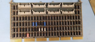
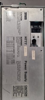
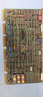
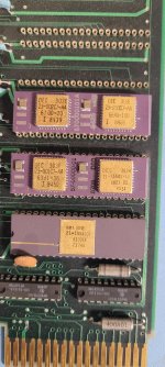
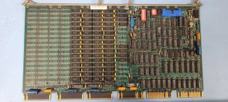
I started working on a PDP11/24, first thing to do is taking it apart, document all boards and take out the power supply.
Then I will open up the power supply, to check all the capacitors.
Then I will open up the power supply, to check all the capacitors.

")

")


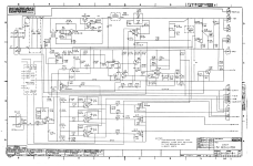
 Schematic and those
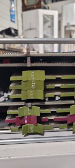
 Power supply connectors.