• Please review our updated Terms and Rules here

PET 2001 repair. Part one: The monitor

QuantumII

Veteran Member
Joined
Aug 12, 2008
Messages
503
Location
Oslo,Norway
Hi,

I just started to look at the PET, and the first thing that needs repair is the monitor.

It currently displays a single horizontal line, sometimes some areas are brighter than others. Maybe this is the PET outputting video.

I have disassembled the screen, and went over the soldering joints for the yoke and some others. It still gives single horizontal.
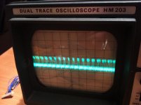
I brought out the scope to do some measurements. I got the below images for the horizontal connectors and the vertical connectors on the yoke. (See attached pictures)

It seems there is a pulse on the vertical as well. Weird. I had to fiddle a while with the scope knobs to see anything, but a pulse is there. Could the yoke be wasted? Connections seem fine too. (Not an open connection, like a broken wire would have caused)
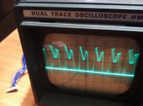
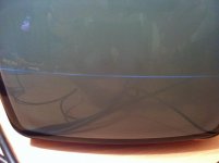
horizontal.jpgpetscreen.jpgvertical.jpg
 
If the yoke would be bad, I guess something driving it has been defective first resulting in too much power for the thin wire.
But I hope it's just a transistor and the yoke should be fine.

There are some scope screenshots in the schematics: I would start at vertical drive in (TTL), testpoint 2 and move forward to TP 5, 6, 14 and 7 and compare each testpoint with the given screenshots. Maybe this shows a bad transistor indeed.

That sounds like a good idea, and I will do it as soon as I can.

Is this the right schematic? http://www.zimmers.net/anonftp/pub/cbm/schematics/computers/pet/2001/video-1.gif
 
It kinda sounds like you're starting at the wrong end with the part least likely to go bad.

Why not take the scope and, starting at the PET side of the video connector, follow the signal through the cable and connectors and then the transistors on the monitor board until it disappears or goes drastically off-spec.
 
Scope waveforms are pretty much useless unless you also know the amplitude of the signal. Adjusting your sweep trigger so you get a clean waveform wouldn't hurt. You could be reading residual power supply ripple.

But I'm with Mike--start at the vertical input of the monitor to see that the PET is sending the right stuff and work your way forward through the chain. You could have something as simple as a bad cable.

Note that there's not the usual synchroguide circuit, but that the PET vertical pulse is merely shaped and amplified. Thus, unless you actually get something from the PET, you'll get no vertical deflection.

It's answers like this that makes a difference. I had no idea that the monitor would require a signal to provide a working raster. Monitors usually do this without a signal (Horizontal and vertical), but the PET monitor actually needs the right input to do this.

Now I see. I will check the video output from the PET board, and see if there is anthing there at all. For all I know, it might output zip zero.

With only AC connected to the monitor, would it do _anything_ at all, or just sit there waiting for a valid signal?
Sorry, I should have mentioned that there's no raster per se; the video output is not required, but you do need the horizontal and vertical drive signals. You have HV and horizontal deflection and it looks like you may also have video, so presumably the problem is somewhere between IC D8-11 and Q9 & Q10 in the monitor. Good luck; shouldn't be too hard to find.
 
Thanks, I will try this when I get home (Trace the vertical drive signal) and see where it ends. I also need to watch out so I don't get shocked by this thing, as the entire monitor is disassembled and is now just the bare PCB and the CRT connected together on the bench.

Are the test points noted in the schematics printed on the PCB, or do I have to follow the circuit to determine where they are?
 
Back
Top