• Please review our updated Terms and Rules here

Pet 8296 blown fuse with monitor connected, and no chirp sound

Link: https://drive.google.com/drive/folders/1fyLbr1kcG98a2FDOMo1H5pj9lIdJpHcx

If you have problems with the link get back to me. The documentation is in there - so please read it...

The fact that you start to get the chirp implies that the Kernal ROM has entered the EDIT ROM successfully.

The 'truncated' chirp (and the potential CRTC programming issue) could indicate a faulty EDIT ROM.

The PETTESTER will yest this theory out...

Dave
 
Thanks i have downloaded all, try with this at 18:00, plese the edit ROM are UC5 or UE8?

It is a 2532 eprom right?
 
Last edited:
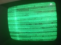
With your rom programmed into 2532 eprom and placed on UE8 socket (by removing the original edit rom) now i have video, but out of vertical frequency, screen flicker vertically and no chirp! But a Signal of video is working.
 

Attachments

  • IMG_20240226_143331.jpg
    IMG_20240226_143331.jpg
    2.9 MB · Views: 3
Last edited:
I have to patch pettest bin file for 80 column? Otherwise, the diag rom stay at this screen and not continue to other tests. I have tested it with 3 different CRTC chip, 2 different 6502 CPU and with my EPROM PLA programmed.

I'm afraid of damaging the monitor leaving it with the v-sync problem
 
Last edited:
Yes, you are correct with UE8. I was looking at the incorrect schematics...

So, this tells me the monitor is OK...

You won't get a chirp. My PETTESTER doesn't chirp at startup. This would be more chips to work that we don't know the state of!

Disconnected the monitor (now we know it works) and let us now concentrate on on the CRTC.

A few people have used my PETTESTER with an 8296 - but I am not sure whether they made any changes to my firmware or not. My PETTESTER is already setup for 80 columns. You need a patch for a 40 column CRTC machine.

With the monitor disconnected, check the frequency of HDRIVE and VDRIVE and post the results.

I have a meeting now.

Dave
 
Can you also check the clocks on pins 21 and 23 of the CRTC (UC9).

Pin 21 is the MUXA/CRTCLK - so if this frequency is out, the HDRIVE and VDRIVE signals will be wrong.

UC9 data bus is directly connected to the CPU data bus. Is the CRTC in a socket or not? If it is, are D0-7 connected correctly via the IC socket?

Dave
 
I check all and then report to you, the CRTC have a socket and CPU too, at the moment only CRTC, CPU, PLA's and ROM are socketed (and the replaced RAM and logic)

Thanks for now and your patient.

Emanuel
 
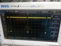
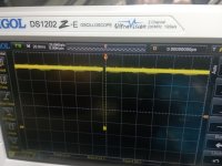
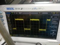
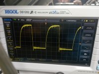
Ok, this is a screen:

172122 is H Drive
172341 is V Drive
172444 is pin 21 of CRTC
172452 is pin 23 of CRTC

The V drive seems to be go away continuosly, i have the waveform only if i set time div very low, otherwise i see a pulse about 1 per second.......

The clock on 21 and 23 seems to be ok, but H and V Drive i think so not!

Emanuel
 

Attachments

  • IMG_20240226_172122.jpg
    IMG_20240226_172122.jpg
    2.5 MB · Views: 3
  • IMG_20240226_172341.jpg
    IMG_20240226_172341.jpg
    2.6 MB · Views: 3
  • IMG_20240226_172444.jpg
    IMG_20240226_172444.jpg
    2.4 MB · Views: 3
  • IMG_20240226_172452.jpg
    IMG_20240226_172452.jpg
    2.3 MB · Views: 2
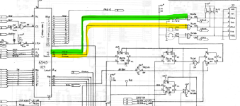
From schematics i don't have signal on yellow wire from CRTC and 7486 (seems GND value), but in green wire i have a positive pulse at 3,91Khz.


1708965468751.png
 
Yes,

But the HDRIVE signal is waaaay to low at 3.91 kHz. This should be 15 kHz or 20 kHz.

Is it really true that you don't have a signal on VDRIVE? As you do appear to have a low-going pulse in post #31. If this is the case, it will be very, very slow. It should have a frequency of 50 Hz or 60 Hz but (if HDRIVE is way to low), VDRIVE could be slower by the same factor...

Dave
 
This Is a little video of what i have on v drive PIN in monitor connector
 

Attachments

  • VID_20240226_175626.mp4
    4.6 MB
OK, i have noted, when i turn on machine i have ADDRESS LINE and DATA LINE pulsing, but after about any second, or in any case a minute, it's stop totally, but video signal stay here.

At this point i don't know what i have to check..... for slowely signals on video connectors.

If possible the cause is the PLA's programmend in EPROM and not original? I have used 27c512 Eprom at 45ns, in this week i have in arrive any 27c512 at 90ms, and now i have only 15ns free to program.
 
So there is something stopping my PETTESTER EPROM from working in that case - so the problem with the PET is more deep routed. I assume pin 7 of the 6502 CPU (SYNC) stops pulsing?

So, you either need to make a NOP generator (or sacrifice a spare 6502 CPU by bending the 8 data bus pins of the CPU out and strapping them to 0V and +5V following the pattern for a NOP instruction (=$EA = 1110 1010)) or purchase a ROMulator from either bitfixer or Nivag.

The latter units have a NOP generator built in with facilities for replacing the ROM and RAM within the machine. They also contain test code (such as my PETTESTER). Check out both units before purchase though and see if they are compatible with your 8296.

Dave
 
Yes SYNC stop pulsing too when stop all other signals on cpu.

I have a 6502 to sacrificate....but i don't know what i have to build for this test
 
Back
Top