• Please review our updated Terms and Rules here

Pet 8296 blown fuse with monitor connected, and no chirp sound

Respectively on UC4 without character ROM:

133700 is UC4 pin7
133724 is UC4 pin 15
133744 is UC4 pin 13

I use same your schematics, now i make image for A to H pins 2,3,4,5 and 10,11,12,14
 

Attachments

  • IMG_20240229_133700.jpg
    IMG_20240229_133700.jpg
    2.6 MB · Views: 5
  • IMG_20240229_133724.jpg
    IMG_20240229_133724.jpg
    2.5 MB · Views: 4
  • IMG_20240229_133744.jpg
    IMG_20240229_133744.jpg
    2.6 MB · Views: 4
Last edited:
And on UC4 without character ROM:

134502 UC4 PIN 2
134522 UC4 PIN 3
134536 UC4 PIN 4
135546 UC4 PIN 5
134622 UC4 PIN 10
134629 UC4 PIN 11
135457 UC4 PIN 12
134707 UC4 PIN 14

All stay about on 1.64v only pin 14 seems to be little difference.
 

Attachments

  • IMG_20240229_134707.jpg
    IMG_20240229_134707.jpg
    2.5 MB · Views: 2
  • IMG_20240229_134629.jpg
    IMG_20240229_134629.jpg
    2.4 MB · Views: 3
  • IMG_20240229_134622.jpg
    IMG_20240229_134622.jpg
    2.3 MB · Views: 3
  • IMG_20240229_134546.jpg
    IMG_20240229_134546.jpg
    2.1 MB · Views: 3
  • IMG_20240229_134536.jpg
    IMG_20240229_134536.jpg
    2.5 MB · Views: 2
  • IMG_20240229_134522.jpg
    IMG_20240229_134522.jpg
    2.4 MB · Views: 2
  • IMG_20240229_134502.jpg
    IMG_20240229_134502.jpg
    2.6 MB · Views: 2
  • IMG_20240229_135457.jpg
    IMG_20240229_135457.jpg
    2.4 MB · Views: 2
Last edited:
Thanks for those traces.

Two observations:

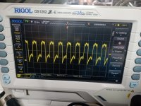
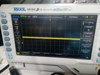
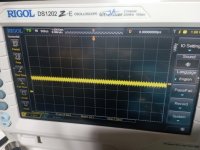
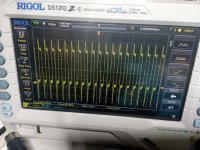
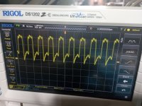
1. Post #101. UC4 pin 7. There is a nasty 'bounce' on the LOW side of the pulse. This is not good. You need to setup your oscilloscope 0V reference to align with one of the major divisions on the oscilloscope graticule so that we can see what voltage things are attaining.

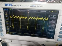
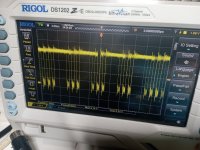
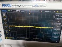
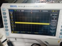
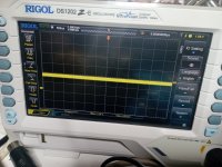
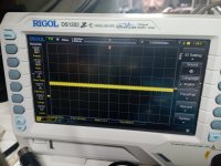
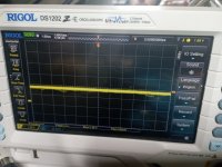
2. All of the signals in post #102 look to be stable voltage levels (no pulsing about). However, their voltage levels (without pull-up resistors are quite low - < 2.0 Volts). This is concerning me a bit on the validity of the results. Can you temporarily install some 1k (or similar) resistors on the data output pins of the character generator (UC5) pins 9, 10, 11, 13, 14, 15, 16 and 17 pulling each resistor up to 5V. You can also use one pull-up resistor to +5V and connect the other end of the resistor to the eight (8) data output pins of UC5. Obviously, this is with the character generator UC5 removed! Is this clear, or do you need some more information before proceeding?

Dave
 
It's clear but I have to organize myself to do this type of test, I can only check pin 7 of UC4
 
No,

Go back to the original configuration of the oscilloscope please.

>>> but I have to organize myself to do this type of test, I can only check pin 7 of UC4.

All you have to do is to connect the oscilloscope probe tip to the ground clip and line up the horizontal line on the oscilloscope to align with one of the major marks on the screen.

UC4 pin 7 is derived directly from the 16 MHz crystal oscillator.

Can you check that UD3 is actually a 74S04 and not a 74LS04

I have to go out now for a while...

Can you remind me which devices you replaced with an EPROM (if any) and is the EPROM currently in your machine or the correct programmable part.

Dave
 
This Is ok? I noticed that when I put the probe on pin 7 and measure with an oscilloscope, if I place my hand on the metal chassis of the machine the waveform narrows in amplitude and changes a lot! but I'm using GND on the probe.

UD3 Is original and Is a 74F04
 

Attachments

  • IMG_20240229_150222.jpg
    IMG_20240229_150222.jpg
    2.6 MB · Views: 4
In my machine i have reprogrammed with EPROM 27C512-4FI the two PLA in position UE5 and UE6 and installed with socket adapter (same adapter of C64 PLA), then all other ROM are originally on programmed EPROM with commodore sticker on top and are the:

UE7 KERNAL/BASIC (i have two of this because faulty in my 8296D 10 year ago and i have burned new one)

UE8 EDIT ROM (i have another of this from my 8296D but i have possibility to reprogram new one if necessary)

UC5 CHARACTER ROM (i have another of rhis from my 8296D but i have possibility to reprogram new one if necessary)

Note: UC5 have originally modification on two pins, is present a bridge from pin 21 to 24 and 21 is lifted from socket.

Note2: i have two PLA UE6 working, but i have tested computer with UE5 programmed and UE6 original, nothing changed, if i remove one or both of this the computer won't boot.

I have ordered a used but working PLA from ebay but probable arrive in 1 month.
 
Last edited:
>>> This Is ok?

Yes. Spot on.

The signal looks a bit strange (having a 'double-dip' from 1.1V down to 0.6V and then back up to 3.xV). The 1.1V to 0.6V swing 'could' be considered as another low-going edge, but I wouldn't class 1.1V (and neither should the device) as a logic HIGH. But we need to keep this in the back of our mind.

The 82S100 ROM has a maximum propagation time of 80 ns. I can't find the datasheet for the specified EPROM you have used. As long as it is no slower than 80 ns - you should be fine. If longer than 80 ns, you could be in trouble.

The signal on UC4 pin 13 is definitely 'strange' (assuming the inputs are all presented with a logic HIGH. Perhaps we need to pull-up the eight (8) signals to UC4 with the 1k resistor (with the character generator UC5 removed).

Incidentally, the pin 21 modification of UC5 is a good modification to have. A ROM is OK with pin 21 installed in the socket. If an EPROM is fitted, pin 21 is no longer a signal line but a power line and requires the modification (bend pin 21 out and connect directly to +5V) to be sure that the video circuitry works correctly.

Dave
 
The eprom are 25C512-4FI, i think so is 40ns, then i have another type model 27C512-12n but i thik so is a 120ns and this model on C64 give me a problem on RAM and stability.

At this point I don't know if it's better to wait for the original ROMs to arrive, or I could desolder the U5 from the 8296D which I have to repair anyway, I don't know if it works but we can try, what do you think? Could the problem I have be with the PLAs on the EPROM?
 
I have checked online the specificati in of my eprom, probable It Is 400ns and not 40ns, and now i have a big dubt of system Is working correctly with this 2 eprom.
 
Nothing, only programmed two new eprom 80ns and with this the computer not boot.

Then I have programmed another two eprom 90ns and not boot

Then I have programmed another two eprom 40ns and it's boot but same of 2 days ago

Finally i have reinstalled two eprom 120ns and same issue with wrong pattern, but i ha e new event today, the screen character blink columns 1,3,5,7..... for any seconds, then all going stop blinking with pettester rom first image (wrong) fixed.

I think so the problem Is generates from this two PLA's , i have ordered original and try with this.
 
Last edited:
Out of anger I took the original EPROMs from the other 8296D and desoldered them, mounted in this 8296 I got the same result. A few days ago I found a faulty RAM in UB5 if I'm not mistaken, I reassembled that RAM and the characters on the first pettester screen as changed......but isn't it like I'm dismantling half the computer and then other RAMs are faulty? I would like to desolder them all and install sockets to test them all one by one.
 
I have desoldered all RAM and tested one to one on a C64, and i have found another fault ram chip on the same bank of first! This chip installed on C64 generate a garbage and flickering screen, similar to 8296! The other one RAM i have found last week on C64 give a black dark screen.

Tomorrow i resolder all chips and replace this faulty with another working and cross finger!

I became suspicious when I remeasured the RAM with an oscilloscope, but I'm still not familiar with recognizing when they are faulty. The first one I found was obvious that the DATA line had a level that was too low and sent the corresponding one from the other bank to the same level compared to the others. , while this one here I honestly don't understand, even in the C64 it seems like it doesn't pulsate on the dataline, but with this faulty one mounted the others also gave the same symptoms, so I don't understand how I could have found it faulty without unsoldering them all!
 
I don't think I can help you anymore with this fix I am afraid.

You are not following the advice I gave you and (in my opinion) you are going backwards.

I am certain you have multiple faults on this machine preventing it from working correctly. As a result it is easy to work on one fault and then get distracted by another.

By removing the character generator, I believe we have identified a problem from the parallel to serial shift register onwards. Once the CRTC has been programmed by the CPU, the RAM and ROM (and CPU) should not have any effect on the displayed image. What we were observing was a strange raster on the screen. We were diagnosing this problem and then you have got distracted by something else...

You certainly should not be desoldering components from one machine and using them in another machine without making a conscious decision to use one machine as a donor for the other machine. Even then, you still not should take this decision likely and without reason.

You would be better off progressing much more slowly and using the time in between to read up on the theory of operation.

Fixing simple faults (or singular faults) can be generally accomplished by the random exchange of parts. Fixing more devious faults and/or multiple faults really requires a logical approach to the fault finding.

I wish you good luck though.

Dave
 
Hi Dave, you're right and I apologize if I didn't follow you, and yes it's true I was fooled by the other problem I noticed but I'll tell you more:

Not only was there another faulty RAM but the problem of block in the first screen of your pet tester was due to the programmed PLAs, now that the computer starts I have tried the original PLAs and everything is fine, only the problem remains that we were analyzing the characters that flash respectively in the odd columns.

While if I install the programmed UC5 and original UC6 PLA the computer works, both with 120ns and with 80 or 90ns, if I install both programmed the computer does not start or starts in monitor mode but without cursor, so surely There is a timing problem between them but that's another matter.

Now that I know that the computer starts thanks to the PLA taken from the 8296D model (don't worry, I won't use it as a donor but that too will have to be fixed but it's worse than this one) I can focus on the problem we had before.
If you don't get mad that I didn't follow you and you help me I wouldn't mind.

At this point we were left to turn on the machine without the 374 and without the character rom with your pettester, which now goes ahead and begins the RAM test.

How do you think I can proceed?
 
I am now confused.

Without the character generator present, how do you know we are getting to the RAM test? Which RAM test?

I need more information about the EXACT details of your machine configuration.

Dave
 
Yes, sorry, I reinstalled everything, char rom and both 374 and now your pettester goes through the first complete character screen, the second with the g character, then go to the keyboard test and complete the countdown, then start the ram test 1 to 6 and complete everything without problems.

The only problem left is that the characters in the odd columns flashing pixels, everything else works normally, if I remove your tester rom and insert the edit rom the computer completes the boot with complete beep chirp chirp now and I have ready prompt with cursor blinking
 
Back
Top