• Please review our updated Terms and Rules here

PET CRT lost vertical

RobbyD

Member
Joined
Jul 25, 2022
Messages
31
Location
Washington State, USA
I have a CRTC PET and the display was working fine for about 30 seconds and then I think I heard a pop and now it simply displays 4 vertical lines with the bottom one flashing (it's the cursor). If I press the return key, the cursor moves down a line. If I clear the screen all the bars go away but I still have the flashing bar. It's as though the entire display has been crushed vertically.
I know the PET is fine because I can connect it to an RGB2HDMI and it's working well. So the problem lies in the VDU.

20221021_112415.jpg

Any ideas? I'm guessing a capacitor?
 
It's most likely it is a capacitor - but not exclusively.

It could have some horizontal issues that you can't see. If it was crushed vertically, I would expect to see some horizontal activity at least.

Have you got a multimeter and/or an oscilloscope?

Can you identify (from the schematics over at http://www.zimmers.net/anonftp/pub/cbm/schematics/computers/pet/) which monitor you actually have.

You will find that most of the monitor schematics incorporate expected oscilloscope traces and multimeter readings at various points on the schematics.

Dave
 
It looks like there are both H and Vertical scan issues. You might get more information turning up the brightness.

If there is a combination of H & V scan defects, as there appears to be, the problem is in the power supply, common to both systems, so check the main DC rail in the VDU first with the meter.

The vertical scan has not completely collapsed. With a total component failure in the vertical amplifier, it usually would.

Apart from the electrolytics drying out, which will cause reduced scan amplitude and scan distortion (poor linearity in the vertical) the most stressed part in the vertical amplifier are the power output transistors. In the 9" VDU's there had fairly inadequate heat sinking, or not at all. I think your VDU is the 12" one and I'm not sure about that one as I have never owned one.

I think your H output stage is working or there would be zero EHT and no screen image at all, but I think it looks "under powered", but like I say if the brightness can be turned up it will give more information, like show a significantly reduced sized scanning raster for example explaining why there are only thin vertical lines visible.

The power supply voltage regulators and or pass transistors tend to run hot in many VDU's and can fail from time to time.
 
Well it seems to be indeed the power supply. I swapped it out with a known good one and it came up. But now I have another issue. The display is waving around almost like it is floating about. When I increase the brightness, you can see what I mean by the waves that are flowing:

20221021_152126.jpg
 
The image shows there is power supply ripple and it is modulating the width, so the DC power rail in the set is not stable, and the amplitude is reduced.

Should be easy to fix, can you post the link to the schematic of your VDU and we can advise where & what to test.

When you said you swapped the power supply out, what are you getting at exactly ? I thought that in these VDU's the power supply rectifiers, filter capacitors & regulator circuitry was on the VDU's board, and not a separate power supply unit. But is it a separate PSU in your particular VDU that you swapped out ?
 
Swapping out the power supply meant that I literally switched out the PET power supply - not just the supply for the VDU. In terms of the circuit for the VDU, here is what I have:
8032 CRT schematic - 321448.gif
PET 8032 CRT Board - 321449.gif
 
So, all the transformer does is to supply raw ac to the monitor voltage regulator on the monitor board. Everything else in the PET (by the sounds of it) is working.

You need to concentrate on:

Bridge rectifier D901.
Capacitors C901, C902 and C721.
Regulator IC901.

Measure the DC voltage on TP1 for 18V. There may not actually be a point marked TP1, but find a convenient point on the output of the regulator. EDIT: I see there should be a TP1...

Switch you multimeter to AC volts, and read TP1 again. You are looking for close to 0.0 volts.

If you have an oscilloscope, probe TP1. It should be fairly close to 18V dc with minimal ripple.

I suspect either a diode has gone in the bridge rectifier, one of the capacitors is not doing its job, or the voltage regulator is going faulty.

There are pretty much three (3) separate systems within the PET monitor - H, V and video. The only real common system that would affect all 3 is the 18V DC power supply.

just out of interest, where are you in the world? Can I suggest updating your profile to include your (rough) location?

Dave
 
ok, so you essentially swapped out the power transformer in the PET computer.

Likely , that transformer is ok and the correct AC voltage is being delivered to the VDU.

As Daver2 suggested, the things to check are the power supply rectifiers in the VDU and the main filter capacitor there and the voltage regulator IC to make sure the 18V is present and stable without ripple.

But, in a sense, even without a scope to verify the 18V supply rail is ok, it is pretty obvious it has ripple on it.

By the look of the frequency of that ripple, on the CRT's raster scan. most likely your filter capacitor on the VDU board , C901, the 3300uF has dried out and lost capacitance.
 
Coincidentally, I had just replaced D901, C901, C902, C721 and IC901. The wavy picture existed before I replaced those parts and remained the same after I replaced those parts.

I did just check TP1 with a meter and it does read 17.75VDC and 0.5VAC

What I find very strange is that the transformer of the PET is making a difference with what I see on the CRT. With the original transformer, I get just the 3 or 4 vertical lines in the center as my previous pic shows. But with the other transformer, I get the full on wavy display. I'm guessing the 23000 MDF capacitor is to blame. I've got some replacements on order.

Assuming I do have ripple and C901 is not at fault, what else should I look for? Diode?

Oh - and I updated my location. Washington State in the U.S.

Thanks a lot for all the assistance. Much appreciated!
 
No, the 23,000 uF capacitor should have nothing to do with the monitor supply. They are completely separate windings on the transformer.

What would be interesting would be to measure TP1 with the old and new transformer.

There could be some sort of weird earth fault? But that is unlikely.

The only other thing I can think of is that it the problem really does originate on the PET logic board - or its power supply unit. In this case, readings from the PET power supply rails would be useful.

Although 0.5 Volts of AC on the monitor supply is actually quite high in my opinion.

Have you got an oscilloscope by any chance?

Dave
 
Last edited:
One interesting thing about working with VDU related problems is, when you can see an image on the VDU face, it is as good, often, as having an oscilloscope, that is if you can interpret what you are seeing.

The scan width for example on a VDU is moderately difficult to modulate dynamically. One way would be to modulate the power supply voltage feeding the H scan stage.

So if you look down the vertical edge of the scanning raster, from top to bottom, if the voltage supplying the H output stage in the set was a constant (as it should be) you would see a straight line. But if it has ripple on it you will see the amplitude (or scan width) in this case altering.

So, if you tip the image of your CRT photo on its side, it is like having an oscilloscope recording of the voltage modulating the H output stage.

Now, because we know what the vertical scan time is (16.66 ms) corresponding to a 60 Hz scan rate and we know that the scanning raster , plus a little extra time to allow for the vertical blanking is 16.66 mS, then from the number of waves or cycles we can work out the frequency of the disturbing voltage, which you can see from the attached diagram repeats about every 8.33mS.

This 8.33 mS is what is known as "Full Wave Ripple". It is what you get out of a full wave rectifier systems, as the ripple voltage across the main filter capacitor C901 (its normal for it to be there), which in the case is twice the line frequency at 120Hz.

Also of note, the scan width is reduced.

How could all this happen and be explained by one faulty part ?

If you look at the circuit of your VDU you will see that the regulator is bypassed by resistors to share the current load and take the heat dissipation off the regulator IC.

The inescapable conclusion is that the voltage regulator IC901 in your VDU has failed (or maybe gone into thermal shutdown) and what you are seeing is the 120Hz ripple from the perfectly good C901 filter capacitor, being coupled via the bypass resistors, to the VDU's 18V supply rail. I would check IC 901's thermal bonding to the heat sink and its solder connections, if ok then replace IC901.
 

Attachments

  • ripple.jpg
    ripple.jpg
    16 KB · Views: 5
I agree Hugo, this is the most likely scenario.

The problem I have is that the OP stated that IC901 has been replaced. All I can think of is that he replaced a duff vr with another duff vr, or there is a PCB tracking fault.

He did say that there 'may' have been a coincident pop...

Nice analysis though...

Dave
 
I agree Hugo, this is the most likely scenario.

The problem I have is that the OP stated that IC901 has been replaced.

Nice analysis though...

Dave
I wonder then if the resistors in parallel with the IC are open circuit and the IC (being ok as replaced) is unable to support the total current and failing to regulate, but it seems less likely.

A measurement of the voltage across C901 might help. It would be unusual that two different power transformers would be providing too low a voltage to get the pre-regulator voltage across C901 up to at least to 21v minimum. Most voltage regulators need about 2.5 to 3V higher than their output voltage to regulate well, unless they are LDO types.
 
Last edited:
I measured resistance across R901 and R902 and it was 25 Ohms.

C901 measures 25.5 VDC

D901 measures 25 VDC across +- terminals and the AC terminals read 10.5 VAC and 11.9 VDC

I went ahead and again replaced IC901 but still no change. And there was a typo above - TP1 measured 0.5 mVAC. (not VAC)

To rule out the PET system board itself, I connected it to a working 8032 VDU+CRT and it came up with no problems. So the problem in this case does seem to lie within the VDU.

Question - what does Q721 do in this circuit? Should I be getting any readings across Emitter and Base? The part that's there now is a replacement (NTE283) - spec is attached.
 

Attachments

  • nte283.pdf
    22.9 KB · Views: 2
Q721 drives the horizontal scan coils and the high voltage circuits.

The base-emitter voltage would only be a maximum of 0.6 to 0.7 Volts.

As you are getting an image, Q721 must be OK.

There is still something not right with the AC input you are measuring.

C901 voltage looks fine (25 Volts for an 18 Volt regulator). A bit high for my liking though...

There is something wrong with your AC voltage measurement however. All of the voltage should be measured as AC and none as DC.

The rectified voltage on the output from the rectifier D901 should be approximately 1.4 times the input AC voltage. 10V * 1.4 gives approximately 14V, not 25 Volts. Hence something is not correct, but possibly with the measurement technique - or the transformer?

Dave
 
...just to double check something, those waves modulating the width of the scan, since we have a photo and not a video, are floating or drifting down the sides of it ? or are they stationary ?

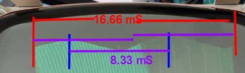
(Q721 acts as a switch and is switched on for about 2/3 of the H scan time and switched off at the right had side of the scan line. When it is off, the CRT beam flies back to the left hand side to start the scan line again and about 1/3 to 1/2 of the scan on the left side is done by damped current via D721, rather than Q721's collector current. Since the width of the horizontal scan line is being modulated by 120Hz ripple, currently we are assuming somehow this is getting past the regulator and modulating the 18V supply feeding the H output transformer and Q721)

It is hard to think that TP1 has close to 18V DC on it and it is free of ripple. Since the H scan width is reduced as well as being modulated by ripple voltage. By the look of the width of the scan I would guess that there is more like 15V or 16V DC on TP1 with at least one volt of ripple superimposed there.

The reason is that the transistor Q721 is a saturated switch (if not it overheats very quickly). The scan width is determined by the time that Q721 is switched on per cycle. This drive signal ultimately comes from the computer as the H drive signal. Once Q721 is switch on, the current rizes at a high rate of V/L Amps per second (but Q721 is not switched on very long per cycle, the peak current at the left side of the scan would be around 2.5 to 3A), where V is the 18v power supply voltage and the L inductance of the yoke's H coils & transformer combination. Since the inductances are a constant, it is the supply voltage V that can modulate the H scan width.

There could possibly be other causes of ripple modulating the H scan width, other than full wave ripple from the line supply, but there are no components there which could easily create a low frequency resonance of about 120Hz and it would seem to be a big coincidence that the ripple frequency seems to exactly match twice the line frequency, which is the type of ripple out of a full wave rectifier system.

The line power frequency of course is not exactly synchronized with the PET's vertical scan frequency, so, if the ripple modulating the width of you H scan is coming from the line power source somehow via the regulator IC, in theory then, it should be crawling down the sides of the scan and not stationary, which is why I asked the question. If the waves are perfectly stationary compared to the scan, then we need to put on our thinking caps.

Please double check that the correct transformer connections are feeding the VDU and double check the AC voltage, that the transformer is sending to the VDU at the input to the bridge rectifier. Obviously, if the AC output voltage of the transformer was too low, 120Hz ripple would break through the regulator, but, since you have changed that transformer already, that doesn't seem likely, unless something else connected to the transformer is overloading it, affecting the output of both transformers you have tried, could be a plausible explanation. As Daver2 pointed out 10V AC is way too low and at best could only generate 14V across C901, a little less too, due to the 1.2v forward voltage drop of the bridge rectifier. Almost like the AC voltage is getting close to about 1/2 what it should be.

You don't have a 230V PET running on 115V by mistake do you ? Check the transformer connections. But that seems unlikely because you said it was working before it suddenly failed. In the case of dual voltage transformers they have two primary windings, placed in series for 230V and parallel for 115V. In this latter case of one of the primaries goes open (or not wired correctly), the transformer cannot source the normal amount of current without its output voltage sagging down.

Just maybe your first transformer was a 115V version and it failed. But the second one you tried producing the raster with ripple was a 230V version. Just something else to check on.

(C902 has to be in good order for the voltage regulator to be stable, worth double checking)
 
Last edited:
If we make the bold statement that there is nothing currently wrong with the VDU, its capacitors, regulator etc are all normal (seems plausible due to the parts being replaced). Then the AC voltage feed to the VDU is too low.

Then the possible explanations are:

1)The transformer is a 230V primary version, being fed with 115v line power. or

2)The transformer is a 115V dual primary type, with only one of the primaries not powered. or

3)The transformer is normal and overloaded by another load. or

4)The connections that power the VDU from the transformer's secondary windings are incorrect- mis-wired to the wrong transformer secondary terminals. or

5) ...Possibly could add; there could be a high resistance in the connections of the AC from the transformer to the VDU a significant voltage drop there, but if that was the case I doubt if the display would be as steady as it is so that seems unlikely.

In all probability, since the PET's 5V supply is probably normal & stable as it booted and the text looks stable (not hum modulated) then option number 4 is the most likely.
 
Last edited:
Back
Top