• Please review our updated Terms and Rules here

PET + simple communication via IEEE-488 GPIB?

blatboy

New Member
Joined
Jan 28, 2023
Messages
9
Location
nyc
Greetings!

I have a PET 4016 (modded as 4032) and I use a petSD+

I'm wondering if it's possible to use the PET as a terminal for a Linux machine (probably Raspberry Pi based.)

I've seen a program available for the PET called PETterm that could work? Would I need an expensive GPIB to USB interface or is there an easier/cheaper route? I don't mind spending some extra cash if it makes it easy, but if there are other ways or if my original idea isn't feasible, I'd love to know from those more experienced than I.

Apologies for my very basic questions here. Thanks so much!

Walter
 
According to the linked website, PETterm bit bangs TTL level serial data on the User Port. You need a MAX232 board to convert the TTL to RS232 and a USB to RS232 converter for the Linux box. You could also use a USB to TTL serial Converter (Adafruit sells one) and eliminate the MAX232 board.
 
Ah... ok. So if I were to use the adafruit TTL to USB... and then just connect pins to the user port as described... maybe using a breakout board like this ---

thanks!
 
Welcome to VCFED @blatboy.

Yes, PETterm just "bit-bangs" on the user port. A TTL/USB converter should be OK - just don't expect too much in terms of serial speed...

Dave
 
I'd be interested to connect my PET to a PI to monitor its console output. I have a bunch of those USB interfaces from Aliexpress used for programming devices, would those work as well?

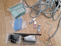
If I understood correctly, a combination of these parts would be sufficient?

petterm-parts.jpg
 
Correct.

Three pins of the USER PORT are used. One for TX, one for RX and the last for GND/0V. Check the PETTERM documentation for which pins are which.

Also triple check what is meant by TX and RX - on both the PETTERM and the TTL/USB converter. Sometimes TX is 'out' and RX is 'in' and sometimes it is the other way around!

Also, make sure that your PET connector has the polarising pin inserted correctly - otherwise it is possible to accidentally reverse the USER PORT connector on the PET edge connector (or to plug it into the wrong port).

From what I remember, PETTERM doesn't use any hardware (RTS/CTS etc.) or software (XON/XOFF) handshake. Double check what your TTL/USB converter requires.

You will also have to match the baudrate of the TTL/USB converter to that of the PETTERM. As no hardware handshake is used - this is what is known as 'transmit and pray' - so don't expect to be able to run too fast (reliably)!

Dave
 
Thanks Dave
Also, make sure that your PET connector has the polarising pin inserted correctly - otherwise it is possible to accidentally reverse the USER PORT connector on the PET edge connector (or to plug it into the wrong port).
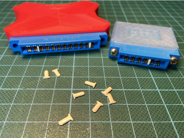
Regarding this, any advice how to buy or make those connector keys that go in between the pins? I've been looking for a solution for keying them to avoid this problem...
 
Thanks Dave

Regarding this, any advice how to buy or make those connector keys that go in between the pins? I've been looking for a solution for keying them to avoid this problem...
If you look at a standard edge connector (socket), you will see small grooves between the socket spring arms. These are designed to hold a narrow strip (barrier arm) of insulating material, that you press in there, to make a barrier, so you can only plug that onto the pcb edge connector where there is a corresponding slot in the pcb that allows the barrier arm to fit. When you flip the connector over, it won't plug in.

Playing around with RS232 links, I have found that the handshaking really doesn't add much, if you keep the Baud rate low, you can just have the Rx and Tx lines only and not bother even with the DTR on sending from the vintage computer to the new one, because the modern computer keeps up with the old one and the buffer doesn't overload, especially if you set a low baud rate like 1200. And if it is set to 1200 Baud, the PET will likely handle it too on receiving data.
 
Last edited:
Thanks Dave

Regarding this, any advice how to buy or make those connector keys that go in between the pins? I've been looking for a solution for keying them to avoid this problem...

I print these and a little dab of glue secures them.


Colin.
 
Oh, I wouldn't need a breakout board... just an edge connector. This is all great info.

My ultimate plan (cue evil laughter) is to utilize the raspberry pi for tcpip/ftp to an external card reader. I won't have to get out of my chair if I want to put something on my petSD card from the internet. Such a pointless venture to keep me from walking across the room (or god forbid, another room) to another computer. But yes, it are these little things that give me joy.

Thanks so much haha.
 
I'd be interested to connect my PET to a PI to monitor its console output. I have a bunch of those USB interfaces from Aliexpress used for programming devices, would those work as well?

If I understood correctly, a combination of these parts would be sufficient?

View attachment 1252337
Oh. I have a similar things (minus the GPIB sockets, which I now have on order) and I will be putting something together like this.

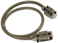
My PETsd uses a GPIB cable with a pass through…

1675182387240.jpeg
I’m hoping I can just keep the PETsd connected when using the terminal
 
+1 above!

GPIB (aka IEEE488) is NOT the same as the USER PORT.

If you look - the two (2) connectors are keyed differently...

Because they are on different edge connectors - the two can be connected simultaneously. No cables (or PET computers) were harmed by this modification (hopefully)!

Dave
 
>>> I wonder if they can co mingle.

That is what I stated back in post #13.

They are on different ports and use different internal firmware/software. They can, therefore, coexist (physically) together.

Dave
 
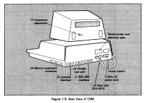
Ahh I'm sorry. I misunderstood. I thought they are on the same physical port (IEEE488 far right port looking at back) as both the PetSD+ and the PetTerm were to be connected. Are you saying the USER port is what I'm thinking is the DISK port in the middle next to the cassette port? Is that where the TTL/USB device would be attached to use with PETterm? That would certainly be better. Sorry for my confusion.
 
1675545942207.png
Oh yes. I was very wrong. Sorry to waste your time on something so simple, that you explained so clearly. I was thinking Parallel (even though I wrote DISK haha) and was stooopidly wrong. I get it. This is great news.
 
So, from your picture...

The PetSD+ (disk) is connected to the IEEE 488 connector (J1).

The PETTERM is connected to the USER PORT (J2).

Now you have to work out which (correct) pins of the USER PORT (J2) to connect your TTL/USB converter to.

Dave
 
I tested this today. The blog post doesn't mention that pin B and C are needed for sending to the PET: https://github.com/ChartreuseK/PETTERM/#hardware

Then it is relatively easy to set up, Rx on the PET goes to Tx on the USB dongle and vice versa, GND goes to digital GND. I tried it with minicom.

Unfortunately PETTERM can't handle my special PET keyboard which is neither graphics nor original business keyboard! All the commands and characters are wrong :-/
 
Back
Top