• Please review our updated Terms and Rules here

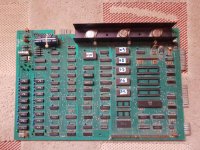
Pet video board 320064-02 bad

It's great that most things are in sockets!

The 5V on pin 1 (video) indicates the PET main board is permanently driving 'BLACK' to the monitor.

Let's assume (for now) that the synchronising pulses are OK (although I do have my doubts).

Can you measure the voltages (with respect to ground/0V) on G11 (74LS20) pins 1, 2, 4, 5 and 6 please. This gate drives the VIDEO signal to the monitor and the output will only be logic '0' (WHITE) when all of the inputs are a '1'. Do any of the input pins look to be permanently '0'?

Dave
 
Be aware of some aspects of the design of your video monitor.

The H drive pulses are not sync pulses. They are the actual drive signal that causes the the horizontal scan circuit, specifically the output transistor Q14, to switch on and off for the correct duration during a horizontal scanning line, and for this to generate both the correct scanning raster (array of scanning lines) width on the CRT face and the correct EHT (extra high tension) voltage for the final anode of the CRT and the correct +85v boost voltage and the correct -30V power rail.

This H drive pulse has to have the correct on-off duty cycle as shown on the schematic (and this is much wider than what an H sync pulse normally is at around 5uS wide). The output transistor Q 14 is often switched on for about 2/3 of the scanning line, perhaps around 40uS and switched off at the end of it, this generates the scanning current for the right hand side of the raster.The scanning current for the left hand side of the raster is derived from recovered magnetic energy of the H yoke coils and H output transformer and passed back to the power supply by the Damper diode CR17. That is why it is sometimes called an efficiency diode too.

Some monitors (not yours) have a separate horizontal oscillator in them and it looks after the tasks described above, and that oscillator gets synchronized with a typical 5uS wide H "sync" pulse. So if the sync pulse is not there, the H scanning and EHT generation is still working.

If your H drive pulse is stuck low or high or not there, due to the AC coupling by C16, then all the transistors Q11,Q12,Q13 will be turned off (not conducting) and there will be no drive pulses to the base of Q14, so no EHT, no 85 or -30V rails.

So the quickest way to determine if the H drive pulse is actually there, and normal, without a scope, is to simply test the 85 and -30V rail to see if they are there and at the correct voltage. If they are not, then you will need to check why, whether the H drive pulse is not there or perhaps there is still a fault in the circuitry of Q11,Q12,Q13, & Q14.

I would suggest making sure the video monitor is working normally before diving into the rest of the computer changing IC's etc. It would be best initially to put every original IC back in (make very sure not to fit any in reverse). Once the CRT monitor is working, or if it is definite that there is an issue with its H & V drive signals, or video signal, then move to fault find the computer board.
 
Last edited:
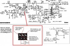
Also, looking at the schematic for the PET monitor, there is an error there. It is only a small error, but it could possibly confuse somebody if they were trying to figure out how the horizontal driver transistor Q13, driver transformer T1 and horizontal output transistor Q14 worked.

The output transistor (Q14 in this monitor) is switched ON by stored magnetic energy in the core of the driver transformer T1, at this time, the driver transistor Q13 is switched OFF. When Q13 switches on again (by a signal that originates from the H drive pulses) this is used to switch the output transistor Q14 OFF. This is done because its easy to switch the H output transistor on, the difficult part is to turn it off quickly and effectively for the start of flyback and this requires power from the driver stage to discharge the base-emitter circuit.

I have attached a diagram that elaborates on the oscilloscope recording of the collector voltage of Q13, to explain it and show that the polarity of the windings of T1 are incorrectly marked (by the dots) on the schematic.
 

Attachments

  • hot5j.jpg
    hot5j.jpg
    99.6 KB · Views: 2
The problem is that (from the dc voltage readings of the H and V drive signals from the PET) is that I don't think that that the H and V signals are working.

Life would be easier if the OP had an oscilloscope.

As a result, I think we need to get some parts of the PET mainboard working to get the initial signals, and then make sure the monitor is working to move forwards.

I agree with measuring the +85V and -30V rails though. However, if they are not present, is it due to a fault in the monitor or no drive signal?

Dave
 
I agree with measuring the +85V and -30V rails though. However, if they are not present, is it due to a fault in the monitor or no drive signal?

Dave

There is in fact a way to know if the Horizontal drive signal is there, without a scope.

If there is no H drive signal there, the voltage at the base to emitter of Q11 (or the base voltage with respect to common or negative or ground) will be zero volts on a digital meter.

However, if the H drive signal is there, there will be about -0.7V for roughly 40us (CR15 conducting) and about +0.7V (B-E junction Q11 conducting) for roughly 20uS.

This means that the voltage at the base of Q11, on the average, if the H drive signal is present, will be about (2/6 x 1.4) - 0.7 = -0.23V.

Which means, with a simple digital meter, if the base voltage on Q11 is negative with respect to common(Q11's emitter) , Then the H drive signal is likely there.If its zero volts, its not there.
 
Hi guys thank for your kindness!
I've checked these:

74ls04:
PIN 1= START 5,2V AND AFTER 2 SECONDS BACK TO 0V
PIN 2= START 0,11V ADN AFTER 2 SECONDS BACK TO 4,6V

7417:
PIN 12=0,12 AND AFTER 2 SECONDS 5,8V
PIN 13=0,12 AND AFTER 2 SECONDS 4,6V


Please
How do I check the 85 -30v line?

Thanks!
 
Hang on, before you do that...

Back in post #15 you stated that you didn't see a reset pulse on pin 40 of the 6502 CPU (the reset signal on the CPU was always high).

7417 pin 12 should be connected to the 6502 CPU pin 40. You are seeing a reset pulse on 7417 pin 12 - but you are not on the 6502 pin 40. Is that correct?

See schematic http://www.zimmers.net/anonftp/pub/cbm/schematics/computers/pet/2001N/320349-1.gif.

There are also some measurements I require from post #21.

Dave
 
Last edited:
Hang on, before you do that...

Back in post #15 you stated that you didn't see a reset pulse on pin 40 of the 6502 CPU (the reset signal on the CPU was always high).

7417 pin 12 should be connected to the 6502 CPU pin 40. You are seeing a reset pulse on 7417 pin 12 - but you are not on the 6502 pin 40. Is that correct?

See schematic http://www.zimmers.net/anonftp/pub/cbm/schematics/computers/pet/2001N/320349-1.gif.

There are also some measurements I require from post #21.

Dave

Dave when i turn on, pin 40 start with 0v for 1 second and after always 5,2 v.....
it's correct?
 
Sorry i've forgotten these:

74LS20 G11:

PIN 1: 5,9V
PIN 2: 2,98V
PIN 4: 0,21V
PIN 5: 0,27V
PIN 6: 3,9V
 
>>> Dave when i turn on, pin 40 start with 0v for 1 second and after always 5,2 v..... it's correct?

Yes, the CPU is being reset correctly.

>>> 7417 it's new....i ve changed with new one.....

When? After post #15?

>>> this is not possible on a working 7417.

Why not? The 7417 is a non inverting O/C buffer.

I am in two minds about the 74LS20 G11. Pin 5 being that low signifies that the VIDEO ON signal is FALSE (i.e. the video is not on). However, pin 6 (the output) is neither high nor low? Let me think about that...

Dave


I've changed 7417 when i ve buy this pet because it was rustly.....
 
>>>
>>> this is not possible on a working 7417.

Why not? The 7417 is a non inverting O/C buffer.

Dave

Ops I'm very sorry Dave, I was thinking about the 7416 which is inverting. Of course the 7417 must be reflecting input to output level as it's a straight buffer. I'm sorry again for the mistake :(

Frank
 
Be aware of some aspects of the design of your video monitor.

The H drive pulses are not sync pulses. They are the actual drive signal that causes the the horizontal scan circuit, specifically the output transistor Q14, to switch on and off for the correct duration during a horizontal scanning line, and for this to generate both the correct scanning raster (array of scanning lines) width on the CRT face and the correct EHT (extra high tension) voltage for the final anode of the CRT and the correct +85v boost voltage and the correct -30V power rail.

This H drive pulse has to have the correct on-off duty cycle as shown on the schematic (and this is much wider than what an H sync pulse normally is at around 5uS wide). The output transistor Q 14 is often switched on for about 2/3 of the scanning line, perhaps around 40uS and switched off at the end of it, this generates the scanning current for the right hand side of the raster.The scanning current for the left hand side of the raster is derived from recovered magnetic energy of the H yoke coils and H output transformer and passed back to the power supply by the Damper diode CR17. That is why it is sometimes called an efficiency diode too.

Some monitors (not yours) have a separate horizontal oscillator in them and it looks after the tasks described above, and that oscillator gets synchronized with a typical 5uS wide H "sync" pulse. So if the sync pulse is not there, the H scanning and EHT generation is still working.

If your H drive pulse is stuck low or high or not there, due to the AC coupling by C16, then all the transistors Q11,Q12,Q13 will be turned off (not conducting) and there will be no drive pulses to the base of Q14, so no EHT, no 85 or -30V rails.

So the quickest way to determine if the H drive pulse is actually there, and normal, without a scope, is to simply test the 85 and -30V rail to see if they are there and at the correct voltage. If they are not, then you will need to check why, whether the H drive pulse is not there or perhaps there is still a fault in the circuitry of Q11,Q12,Q13, & Q14.

I would suggest making sure the video monitor is working normally before diving into the rest of the computer changing IC's etc. It would be best initially to put every original IC back in (make very sure not to fit any in reverse). Once the CRT monitor is working, or if it is definite that there is an issue with its H & V drive signals, or video signal, then move to fault find the computer board.

Please Sir, where can i measure 85 and -30v??
Thanks!
 
-30V across C22 (47 uF 50V).

+85V across C27 (3.3 uF 200V).

Be careful, you are in the monitor with lots of high voltages around.

Meter set to dc Volts with a suitable full-scale range.

Dave
 
-30V across C22 (47 uF 50V).

+85V across C27 (3.3 uF 200V).

Be careful, you are in the monitor with lots of high voltages around.

Meter set to dc Volts with a suitable full-scale range.

Dave


Strange values....

C22= 0v Dc
C27= 14v Dc
 
The question is do you have no Volts here because you have no horizontal drive signal from the PET logic, or because of a fault in the monitor?

What is the cause and what is the effect...

Dave
 
Back
Top