• Please review our updated Terms and Rules here

Power Supply dead

Update

Update

I found somebody nearby me who maybe could fix the power supply. I turned in the power supply last week, and I got it back today. I was told the power supply wasn't dead, and it seemed like it worked fine.
Nevertheless, the 'light button' on the keyborad doesn't light up, and the two floppy disks I have doesn't spin either.

So what is then wrong?


Vifa
 
Well, now...

It's time for you to break out the multimeter and check the power supply when it's plugged into the computer and turned on.

Set the multimeter to DC volts. If it isn't autoranging then choose the 20volt setting.

On the 4116 DRAM chips pin 16 is ground. Put your black lead on it. Put the red lead on pin 1 and you should read -5v. Put it on pin 8 and you should read +12v. Finally, on pin 9 you should read +5v.

If one of these is missing then the power supply or power jack is messed up.

If they ALL are missing then you may have a short on the motherboard or an expansion card. Unplug all cards one by one and see if the system powers up. When you find the bad card, report back here.

If all the cards are out and it's still dead, you may have a short on the motherboard.

To check for shorts... use a DIGITAL multimeter. DO NOT USE ANALOG. Put it on the continuity test function.

Go back to the 4116 DRAM chip. Put the black lead on pin 16. Put the red lead on pin 1 then 8 then 9. If you have less than 10 ohms to ground then you'll have a shorted part on your hands. Most likely it will be one of those tiny capacitors on the +12v line and your 12v line will show a short. I've seen that before.

RJ
 
Hey there. I finally got a voltmeter.

I assume the 4116 DRAM chips are the ones inside the red box I have drawn in the attached picture, right?

I am not sure which pin is number 16 and which one is number 1, I tried to find a datasheet but with no luck. How can I tell which pin is 16 and which one is 1?

I tried to put the black lead and the red lead on what I thought was pin 16 and pin 1, but I am not sure it was, something strange 'clicking' sounds/noise then came from the power supply. Not loud, but you could easily hear them.

Before I go further on, please help me find out where pin 16 and 1 is.

Vifa
 

Attachments

  • DSC014641.jpg
    DSC014641.jpg
    111 KB · Views: 1
Hey there. I finally got a voltmeter.

I assume the 4116 DRAM chips are the ones inside the red box I have drawn in the attached picture, right?

I am not sure which pin is number 16 and which one is number 1, I tried to find a datasheet but with no luck. How can I tell which pin is 16 and which one is 1?

I tried to put the black lead and the red lead on what I thought was pin 16 and pin 1, but I am not sure it was, something strange 'clicking' sounds/noise then came from the power supply. Not loud, but you could easily hear them.

Before I go further on, please help me find out where pin 16 and 1 is.

Vifa

Code:
      [--U--]
Pin1 -[¤    ]- Pin16
     -[     ]-
     -[     ]-
     -[     ]-
     -[     ]-
     -[     ]-
     -[     ]-
Pin8 -[     ]- Pin9
      [-----]
 
Last edited:
There's a notch on the chip to help you identify pin 1.

If you are hearing a clicking sound coming from the power supply then there is a short somewhere on the board. Skip checking the voltages and jump right into testing continuity to see which power line has the short.

Do the continuity tests with the computer OFF.

Code:
16     9
--------
)      |
--------
1      8
 
All right then.

Now when I know where pin 1 is located, I have tried to do what you (channelmaniac) told me to do - and the situation is as:

---------------------------------------------------------

Black lead on pin 16 and red lead on pin 1: Nothing

Black lead on pin 16 and red lead on pin 8: it sparks, and the clicking noise from the power supply appears again.

Black lead on pin 16 and red lead on pin 9: it sparks, and the clicking noise from the power supply appears again.

---------------------------------------------------------

I have tried with other of the chips and the situation is the same.
 
sparks

sparks

You're sure you're checking continuity (resistance) and not current, right ? And with the power supply unplugged from the board ?
Sparks are not good when testing with a multimeter.
patscc
 
All right then.

Now when I know where pin 1 is located, I have tried to do what you (channelmaniac) told me to do - and the situation is as:

---------------------------------------------------------

Black lead on pin 16 and red lead on pin 1: Nothing

Black lead on pin 16 and red lead on pin 8: it sparks, and the clicking noise from the power supply appears again.

Black lead on pin 16 and red lead on pin 9: it sparks, and the clicking noise from the power supply appears again.

---------------------------------------------------------

I have tried with other of the chips and the situation is the same.
Note that not all of the IC's are using pin 8 and 9 as power sources. However, I'm not sure of the pinouts of the rest of them.
 
You're sure you're checking continuity (resistance) and not current, right ? And with the power supply unplugged from the board ?
Sparks are not good when testing with a multimeter.
patscc

No, so far the multimeter has been on 20v.

But I will do the continuity testing right now with the power supply unplugged.
 
4116 pinout

4116 pinout

pin 1: -5 V
pin 8: 12 V
pin 9: +5 V
pin 16: Ground.

You should measure any voltages with respect to ground. Preferably by clipping the black lead with an aligator clip to system ground somewhere, this way you don't have to balance two probe tips against the ic.

The rest of the pins:

pin 2: Data in
pin 14: Data out
(remember, it's organized 16k x 1)
pin 5: Address 0 (lsb)
pin 7: A1
pin 6: A2
pin 12: A3
pin 11: A4
pin 10: A5
pin 13: A6

pin 3: Write enable
pin 4: Row address strobe
pin 15: Column address strobe

Where they hefty sparks, or real tiny ones ?

post if you have troubles tracking down pinouts.

patsc
 
pin 1: -5 V

Where they hefty sparks, or real tiny ones ?

patsc

Most of them were tiny ones, but there were also some sparks that you might call a little bit hefty. Is this serious? I mean, can any damage have been done?

Anyway, there is something wrong with my multimeter...:( 
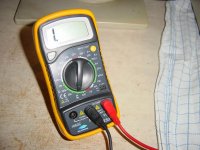
I will borrow another one tomorrow; but the question is then if I shall start all over with putting the multimeter on 20v (even though there were sparks from pin 8 and 9 when I just tried with the bad working multimeter) and start all the testing again?

So far, I have had the multimeter on 20v and tested pin 1,8 and 9 with the black lead on pin 16 and the power supply plugged in. Then I have had the multimeter on the continuity where I couldn't read anything at all, probably because of the bad multimeter I have borrowed.


I really appreciate you effort to help me, so far thanks to all!...:)

Vifa
 
Are you sure you are using your meter correctly?

If you are on the 20A scale instead of 20V you'll short things and get sparks.

Also, if you have 3 holes for leads on your meter, make sure you are using the +DC volt one and not the DC Amp one or you'll short things there too. (My Radio Shack meter is like this)

RJ
 
Also, it sounds like your power supply is working if you are seeing sparks. ;)

Do you have a logic probe? If you have nothing on the screen but yet have power, I'd suspect a bad crystal. It's not too uncommon on the old Apples. In the USA it's a 14.31818MHz crystal.

RJ
 
multimeter

multimeter

Can you post a picture of your multimeter, the way you had it set up ?
It really does sound like you had it on a current seeting (uA , mA or A ), or the leads connected incorrectly. That it suddenly has a problem supports this thought, since current inputs are typically fused, and it sounds like you might have blwon the fuse.
patsc
 
The multimeter I have borrowed is one of those with three holes, and I had probably plugged the leads wrong (it is working now ;)). The picture shows how it is plugged now.

I just did some testing on the resistence, I had the multimeter on '2K'.


The black lead on pin 16 and the red lead on...

---------------
pin 1: 0,725
pin 8: 1,1
pin 9: 0,178
---------------


Vifa
 

Attachments

  • DSC01474.jpg
    DSC01474.jpg
    105.3 KB · Views: 1
looks good

looks good

Ok, now that you've go it set up, change the range to 20V and plug in the pwr supply and measure the pin voltages. Remember, use a clip or something to clip the black lead to ground.

patscc
 
Ok, now that you've go it set up, change the range to 20V and plug in the pwr supply and measure the pin voltages. Remember, use a clip or something to clip the black lead to ground.

patscc


I have just done it with the 20V and power supply plugged in:

With the black lead on pin 16 and the read lead on...

---------------
Pin 1: (-5,7) - (-6,3)
Pin 8: 11,8 - 12
Pin 9: 4,95
---------------


Vifa
 
Hmmmm... that -5v is way out of whack.

So you have power, but you have nothing on the screen? And the computer doesn't beep when you turn it on?

What are you using for a monitor?

RJ
 
Ac

Ac

Pin 1 is actually above the spec for the part.
Ok, now, set your multimeter to AC( 20 V range ), and let's see if perhaps you've got excess ripple coming through on one of the supply legs.
When you post the results, make sure you specify if it reads mV or V

patscc
 
My monitor is an Apple /// Monitor.

But nothing seems to happen when the power is on. No light in the 'light button', the floppy disks don't spin and the monitor shows nothing.
 
Back
Top