• Please review our updated Terms and Rules here

Power Supply dead

Pin 1 is actually above the spec for the part.
Ok, now, set your multimeter to AC( 20 V range ), and let's see if perhaps you've got excess ripple coming through on one of the supply legs.
When you post the results, make sure you specify if it reads mV or V

patscc

Problem is that it's a switching supply and his voltmeter may not even read the ripple as the frequency will be very high.
 
My monitor is an Apple /// Monitor.

But nothing seems to happen when the power is on. No light in the 'light button', the floppy disks don't spin and the monitor shows nothing.

Well, you have voltage to the board. Here's where you need a logic probe.

Replace the crystal and see what you get. You should at LEAST have a bunch of garbage on the screen at this point. The clock circuit is probably down.

Don't go by the light on the keyboard as they can burn out. If you have no clock circuit then I doubt the floppy drives would even light up at this point.

I don't have a logic probe at home, but I can get one tomorrow. I am not sure where the crystal is located and what it looks like - can you point it out in a picture?
 
-5 volt leg

-5 volt leg

Does the -5 leg actually come from a switcher, or from a linear regulator in the power supply since it's such a low-current leg ? Common configuration in a lot of older power supplies, HOWEVER, I don't know about the Apple, so if someone could point me to a schematic...
Anyway, Vifa's got a multimeter, so that's what we'll use 'til we run out of ideas.

You can take the multimeter to the lowest address pin of a DRAM, or of the processor, and you should get a reasonably constant AC signal around 2.25 or so VAC (multimeter's averaging of the pulse train over time, try it on known good one)

patscc
 
It's all from the switcher on the Apple.

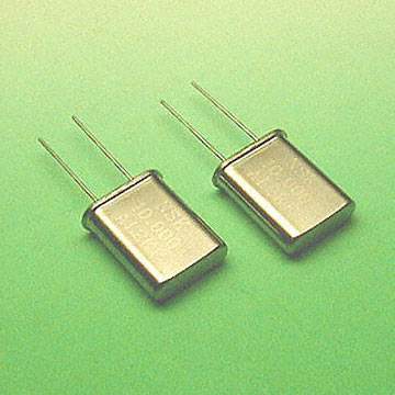
The crystal looks like this:

product1.jpg
 
I will continue my work tomorrow.


I count on getting a logic probe tomorrow, can you describe what I shall do when I get it?

I think I have found the crystal too, it is placed in the row on the motherboard which is called 'A', right? Anyway, how can I get to replace this? and with what?


Vifa
 
Crystal & PSU

Crystal & PSU

I should think that before any crystals get checked or replaced, an effort should be made to see if the -5 V leg is indeed functioning correctly, since the crystal has no effect on the PSU, but the PSU has an effect on the rest of the computer.
Does anyone have a schematic or something with what the voltages should be, and what range the allowed fluctuation is ?

patscc
 
The 4116 DRAM spec sheet calls for -4.5 to -5.5 so the power supply will need some repair work, however, even with it out of spec there still should be some sign of life on the monitor.

Since there is absolutely nothing, I think the crystal or the chip driving it is bad.
 
Clock

Clock

That's why I suggested the measurements with the AC range of the multimeter on an A0 line, if there's activity (i.e. if the clock's running) there's be an AC voltage around 2.25 or so.
patscc
 
That's why I suggested the measurements with the AC range of the multimeter on an A0 line, if there's activity (i.e. if the clock's running) there's be an AC voltage around 2.25 or so.
patscc

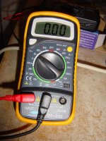
I will try to do this, but I am not sure how my multimeter shall be set. The picture shows how I assume my multimeter shall be.

Then, where shall I measure?
 

Attachments

  • DSC01484.jpg
    DSC01484.jpg
    109.4 KB · Views: 1
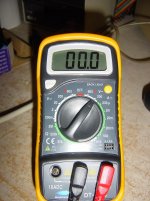
Right, I have attached a picture of how the multimeter now is set. With this setting I have done what you told me to, and if the black lead is on pin 1 and the red lead on pin 5 I read 11,5; if the red lead is on pin 1 and the black lead on pin 5 I read 4,2.

I am not sure whether not it says mV or V, nothing appears to indicate it.
 

Attachments

  • DSC01492.jpg
    DSC01492.jpg
    106.6 KB · Views: 1
pins

pins

Your meter appears to have a rather coarse resolution on AC.
You want the black lead against ground, or pin 16 on the 4116, and then measure pins 1 & 5 with the red lead.

patscc
 
Of course, just did the testing again.

Pin 1: (-00.1) - (-0.00)
Pin 5: 00.0 - 00.1
 
Pin 4: (-00.8 ) - (-01.0)
Pin 15: 08.7

The first row of DRAM chips (row C) are all reading 04.6 on pin 15. But it also looks like these are a bit different.
 
Last edited:
Well, without having any real test gear or knowledge of troubleshooting... the only thing left to do is either send it to someone that can repair it or take a last ditch effort of replacing the crystal to see if you can end up getting something, anything showing on the screen.

Raymond
 
Aple II probs.

Aple II probs.

What can I do now?

Hi
Been following your progress.
Really you should be checking your Power supply properly.
The Astec PSU is the same for Europe as the US. The
110V/220V link decides. Your PSU has been worked on previously as the
switch has failed and is bypassed.
Apple clones coppied the same or similar circuit and board layout.
Early 8088 clones even used this same circuit. It is a good one.
These PSU do not work "off" the machines. They need to
be loaded. The clicking you hear is the switch mode ramping up but
then dying as the transformer saturates killing the cycle.
It will continue trying. Open circuit (no load) or shorting will
cause this to happen. Some PSU have adjustable +5V o/p
If this is set too high the +12v crowbars and shuts the PSU down.
There is a 6 pin connector onto the motherboard.
The 2 black leads are Earth.
There is a +5v.+12v, -5v, and -12v.
These are the safest places to test for voltage. Use a paper clip
pushed down the hole with the wire. Use 2 clips. Use one clip in
one of the black earth wire holes and use the other paperclip wire to
check the other wires for voltage. The colours are usually
Orange = +5V, Yellow = +12V Green - 12V Blue -5V.
If it is the PSU you will have to desolder/resolder components.
The clicking and sparking shows that the main fuse is ok
and there is some PSU activity.
Be very careful testing the components on the motherboard
as if you slip you can short bits and damage them. The arcing you mention
is not good.
The PSU electrolytic capacitor mentioned as a prime suspect is
if I remember right C7 (220uf/10v)
Best of luck
Scommstech
 
Back
Top