• Please review our updated Terms and Rules here

Power Supply will no bring up Unbranded 286 Motherboard

alejack12001

Experienced Member
Joined
Jul 26, 2020
Messages
424
Location
Fredericksburg, VA
I am using an unbranded 286 motherboard that I recently acquired for an IBM 5162 machine to replace an AST motherboard that was faulty. The AST board worked with a 130-W power supply that accompanied the 5162 received. Power supply was good at least under the AST board.

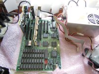
The attached picture, labeled DSC0002.JPG, shows the motherboard that was sold to me by an eBay seller. If you notice, the sellers power supply that was used to demonstrate the actions of the board as being operational, was a converted 20-pin to 12-pin supply to power the board during this demo less a chassis ground to the board other then the grounds through of the power connector.

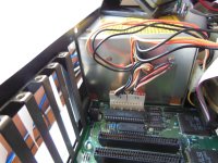
The problem is when I flip on the 5160’s 130-W Power Supply power switch, the board doesn’t respond. The fan, which is on top of the power supply doesn’t spin up. First, I thought it was a grounding issue since the seller didn’t have a chassis ground and I did have a chassis ground with a screw seen in picture DSCN0034.JPG. I checked the board using a continuity checker on my DVM and removed the screw anchoring the board to the chassis as well as removed the power connectors and then checked ground points I could find such as the ROM’s. I found that no chassis grounds were detected. When I reconnected the power connectors a ground reappeared. I have ruled out a grounding issue.

I don’t know if there is a fuse in this power supply or not. No schematic on this supply except for one posted on minuszerodegrees.org website. The posted power supply schematic didn’t show one and I am unsure how true to form the 5160 power supply that I have matches the actual 5160 shown on the website.

I was going to reproduce the setup that the seller tried to see if the board and power supply responds. This will prove a possible short between the board and chassis. I have the board raised on those nylon stands for most of the holes in the board. The next picture shows the same board in the 5160 case, labeled DSCN0034.JPG. I have a case connected screw that is shown near the power supply connection.

I am looking for advice and other users experiences here. I know there is multiple power supply threads on the forum with some match and many others that are similar, but with different platforms.
DSC0002.jpgDSCN0034.jpg
 
I see several tantalum capacitors on the board. Odds are one or more of them is shorted. Find which one(s) and replace. I wouldn't get too upset at the seller, this kind of thing can happen from one day to the next.
 
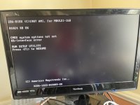
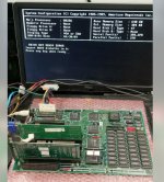
I ran the test using the seller's procedure with a picture shown as DSCN0036.JPG. The machine came up as seen in this picture IMG_4066.JPG. So it is a short circuit and grounding something. No fuse problem. I don't know where it is shorting though. I new mystery for this machine. In addition by means of IMG_4066.JPG, the machine doesn't doesn't seem to like my Type F keyboard. That is a little weird but for another thread. What can I use as insulators for this board and should I use a nylon screw to hold the board down?

DSCN0036.jpgIMG_4066.JPG
 
Were type F keyboards XT keyboards? I recall your previous Ast Xformer was a 5160 replacement so I’m guessing it was designed with an XT keyboard in mind rather than an AT one.
 
Were type F keyboards XT keyboards? I recall your previous Ast Xformer was a 5160 replacement so I’m guessing it was designed with an XT keyboard in mind rather than an AT one.
Yes, you are right the type F is an XT and the board I am probably dealing with is looking for an type M or AT version.
 
Bear: I am not upset with the seller; actually I am grateful for his procedure. I just used his procedure to show that the board was operational. I repeated his procedure to effectively get the board up. I just need something that will help me know insulate the board from what appears to be a short between the board and the case causing the short.
 
early systems sometimes had plastic pop-in supports that slid into keyhole shaped slots on the case bottom then the remainder of the support holes used brass thread-in supports with metal screws but many times they used fiber washers that were reddish-brown between the screw head and the board. If you have only threaded holes for posts you might have to start by setting the board in place then put one screw down to hold it and see if it starts. If it does go to another hole and try it. If/once you find a screw causing a short then you might have to remove that support post and leave that hole without a post and screw.

Edit: I just looked back at your photo of the board out of the case and it seems your board has the plastic supports, do they all have keyholes they can go into in the case?
In the middle of the case and along the top near the expansion slots the are both an oblong openings that narrow and some round openings. The nylon tops that you see on the board have a large round disk coupled with a smaller disk below it that slides into those oblong slots. Near the end of the case there are three i/2 distance oblong slots that are open ended, which would accept the nylon mount you can see in the picture. I am sure now that I cannot use the screw mount as the mount pulls the motherboard too close to the expansion slot are making it difficult to attach the expansion board like the floppy/hard drive controller. Yet, I don't think these are shorting. However, I think the problem I am having deals with the 5160 case. The case was designed for a XT type machine and not the 286-AT type I am putting in. There is a vertical U shaped bracket that is below the disk drive bay. The U shaped bracket that is part of the disk drive bay and made of metal, which is welded to the case. I think that IBM made this bracket to hold their board up but placed a plastic sleeve over the board to protect the board circuits from shorting or grounding or coming into contact with the U shape bracket. When these cases are being refurbished, the plastic sleeve gets dis-guarded. I think what I need is a sleeve to protect the board from coming into contact with the U shaped bracket.
 
I haven't had a 5160 apart in a while and that's the case IBM used in a 5162 I believe. But I'm in the middle of tinkering with a 5150. The motherboard mounting should be similar. At any rate, not all of the holes had those nylon standoffs. Two on the right have the "use for almost everything" #6-32x3/8" machine screws. Perhaps more importantly, the one in the back by the power supply had a nylon washer between the MB and the screw head. I thought that odd, because it isolated the screw head from a rather large solder (ground?) pad on the top of the MB. Why put the pad there then insulate it from the screw (chassis) with a nylon washer? Anyway, the PS started up fine before I took the machine all apart for cleaning, so I put it back the way I found it. The machine is just about all back together except for a half height drive standing in for a full height that I need to fix. Bottom line is it is running fine with the nylon washer there.

Just some food for thought. Maybe try insulating that hole first.
 
Keep flicking the power supply on and off and see if the fan budges at all. Its normal for these power supplies to get a little finicky due to their age. Just ran through a similar situation with a 5162 chassis, but mine would power up, but wouldn't power the board. Make sure to throw a few hard drives on the molex connectors for load. Once it starts, let it run a good long while.
 
This reminds me - I once put a tiny Juko XT motherboard one time in a random AT case and I had this same problem. I was sure there was some random short, but it was infrequent. There was some part of the motherboard i could put some weight on to make the problem go away, but I never found where the short was exactly. Ultimately I was lazy and fixed the issue by just taping up and down the bottom of the interior of the case with some nonconductive adhesive tape (this brown/copper colored tape, i've heard it called Kapton Tape) and the problem went away. Sort of a bandaid approach but worked.
 
This reminds me - I once put a tiny Juko XT motherboard one time in a random AT case and I had this same problem. I was sure there was some random short, but it was infrequent. There was some part of the motherboard i could put some weight on to make the problem go away, but I never found where the short was exactly. Ultimately I was lazy and fixed the issue by just taping up and down the bottom of the interior of the case with some nonconductive adhesive tape (this brown/copper colored tape, i've heard it called Kapton Tape) and the problem went away. Sort of a bandaid approach but worked.
It's worth a try to see if it prevents the shorting.
 
My standard method for testing motherboards is to put them on a piece of plywood along with the PSU, making sure that they power up successfully. Then I grumble about putting them in a case. You can get short circuits from the oddest places. My latest adventure was a "baby AT" case that had raised parts of the base plate to accommodate screws. One of them contacted one of the power busses. I remedied it with a fiber washer glued to the offending part.
 
Ya on my XT chassis I use electrical tape over the 2 rails to prevent shorts. I use cardboard mailer boxes but same idea Chuck. (y)
 
See if this idea has merit. The board in question measures 13.125 inches by 8.625 inches. So, my thought was to cover all the connections under the board by using clear slide plastic. I have some of these left over when I used to teach college. I would have to use two sheets since the board is long and a little wider than the plastic, cut and paste. I could insert holes to mount the nylon board mounts. I'd still have to find something to cover the edge where the U shape board mount reside, but I may have a work around for that.
 
Back
Top