• Please review our updated Terms and Rules here

PSU help!!!! (Transistor identification)

Nama

Veteran Member
Joined
May 22, 2009
Messages
857
Location
New Zealand
Hi all, a friend and I have been working or resurrecting a 5160 PSU (220v). It's been a mission!

We have replaces a number of components that were either obviously dead or corroded and crumbling.
Unfortunately, still no luck getting it to work.

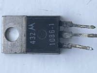
I was wondering if anyone recognises this part (see attached), and what would be a modern main switching transistors replacement.
The two on the board are dead, so I got some some J13007 transistors as we I thought they would work well...now it looks like these replacement transistors are not compatible as they do not switch on, even with the drive on the base looking ok.

Anyway, if anyone can help with identifying a modern replacement would be most appreciated.

Thanks
tempImageO9abI8.png
 
I was wondering if anyone recognises this part (see attached)
Obviously Motorola made, but I could not identify the part based on the numbers.

and what would be a modern main switching transistors replacement.
Without a circuit diagram, how did you determine that the two transistors are being used as switches ?

And how do you know that they are transistors? For example, maybe they are FET's.

I got some some J13007 transistors
Assuming that the Motorola made part is a transistor, with that part presently unidentified, how did you establish which pins are base, collector, and emitter ?

The two on the board are dead,
Two doesn't sound right. How did you determine "dead".

Anyway, if anyone can help with identifying a modern replacement would be most appreciated.
Unless the Motorola made part can be identified, as I see it, what would be needed is:

1. You draw out the circuity around the subject Motorola made parts, including component values, and if possible, supply voltages.
2. Someone with enough electronic engineering knowledge, analyse your circuit diagram, and from that, work out the characteristics of a replacement part.

And maybe quite a bit of the circuit diagram will be required.

Maybe your power supply matches the circuit diagram at [here]. (One main switching transistor - top right - "Q10 OSC OUTPUT".)
 
Thanks for your reply:

“Without a circuit diagram, how did you determine that the two transistors are being used as switches?”
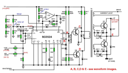
Seems very similar to the 5155 PSU diagram found here:
https://slx-online.biz/hursley/docs/5155_psu.pdf
…and have been using that as a general guide. Parts in question match Q1 and Q1.
Specifically here:

371536534_866863711655304_3128693655320610843_n.png
_____________

“And how do you know that they are transistors? For example, maybe they are FET’s.”
The linked 5155 PDF above states they are transistors.
_____________

“Assuming that the Motorola made part is a transistor, with that part presently unidentified, how did you establish which pins are base, collector, and emitter?”
It’s marked in the top side of the PSU PCB.
______________

"Two doesn't sound right. How did you determine "dead"."
Tested using multimeter with parts removed.
______________

I’m pretty hopeless at this analog stuff, but my friend is pretty spot on with it, as he used to repair PSU and CRTs (among other things) back in the day.
 
Last edited:
If that's the schematic and the TO-220 in question is Q5, then just about any NPN that's rated for use as a horizontal output transistor for TV use should work.
 
Ok...some more time has been spent with the PSU.
So here is what it does:
If powered up off 220vac mains, Q1 and the 12v regulator both get killed (these two are obviously in very different parts of the circuit!!!), Q2 seems like it never dies.
If the PSU is brought up slowly using a Variac to 120vac the powersupply will work fine with good 12v and 5v output.

I'll get back to you re: DC emitter-base voltage.

Cheers
 
What does the line-side supply look like? Some of these old PSUs would jumper the rectifier on 120VAC to serve as a voltage doubler, while on 220V, it would be a normal full-wave configuration. If it were doubling the 220VAC input, that would explain the failure.
 
What does the line-side supply look like? Some of these old PSUs would jumper the rectifier on 120VAC to serve as a voltage doubler, while on 220V, it would be a normal full-wave configuration. If it were doubling the 220VAC input, that would explain the failure.

Thanks, yes that's been checked. It's full wave no doubler
 
Ok, just for completeness I will wrap up this thread.
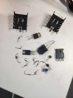
John (I can't take any credit at all) finally got the PSU working! It was another monumental effort where we even considered gutting it and putting in a modern power supply. In the end John found more dead parts (mostly diodes) which finally stopped the transistors from continuously blowing on power-up.
Quite a few dead parts...what originally happened to this thing???
On another note, when first I got this 5160 every single RAM chip was dead (as well as a couple of other components) that is quite an achievement considering it was fully populated.

370201255_1318185708866332_6703667460910521039_n.jpg
 
Power line struck by lightning?
Yeah maybe...Can't think what would have caused all this damage...Maybe one component failed and then there was just a cascade of failures from that...The last thing I realised that had also failed was the 12v fan :-(
 
Back
Top