• Please review our updated Terms and Rules here

QProbe 2023

Matlock

Experienced Member
Joined
Jan 12, 2013
Messages
172
Location
Canyon Lake, Texas USA
All,
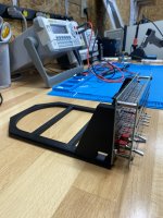
Today I just got my DHL package from Joerg Hoppe with his new QProbe 2023.

See http://retrocmp.com/tools/qprobe/327-qprobe2023-overview for details.

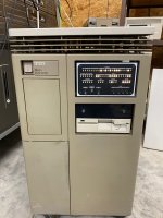
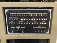
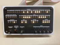
The external display panel with its PDP-10/12/15 drive bay styling looks great and the incandescent bulb appearance of the LEDs in action looks fantastic. I installed it on my BA123 PDP-11/83. My favorite thing about PDP-11 console displays was having the RSX11M light pattern run while the system is idle. To get that pattern to display on the original QProbe or this new display, you need a CPU with cache (11/73, 11/83) and you need the memory access to run through the Q22 bus. PMI memory on a 11/83 still shows activity when there is I/O but the PMI memory traffic from the CPU is not visible. However, put the CPU in Slot one and memory in slots 2 and 3 and everything works fine. You do loose a bit of performance but the display is MUCH more fun!

Do take a look at Joerg's in depth YouTube video
to see the capabilities.

Now my Qbus PDP-11 no longer has "Blinken Light" envy of his older Unibus siblings.

Best,
Mark
 

Attachments

  • IMG_4362.jpg
    IMG_4362.jpg
    689.6 KB · Views: 28
How fun. Now to decide if my 11/83 in the BA-23 will fit the drive bay panel...
 
Looks great. I preordered one ywsterday. Joerg, I was wondering if the drive pay panel display will tolerate longer cables - I don't have any free bays, I'd like to mount it in a box to put on my desk instead.
 
I am trying to figure out how to put that 5.25 front panel on my H11 without cutting on the case.

I guess I'll have to put it in an external enclosure, but I guess that's ok. I have an open space in my H-17 enclosure, but then the whole thing would be sideways.

Hmmmmmmmmm.........
 
Looks great. I preordered one ywsterday. Joerg, I was wondering if the drive pay panel display will tolerate longer cables - I don't have any free bays, I'd like to mount it in a box to put on my desk instead.
The cables sit between the driving CPLD and the LEDs. They have no influence on QBUS impedance, can be a mile long.
 
Looks great. I preordered one ywsterday. Joerg, I was wondering if the drive pay panel display will tolerate longer cables - I don't have any free bays, I'd like to mount it in a box to put on my desk instead.
"Sideways" is a topic. I've no idea for a "portrait" blinkenlight layout, never seen one for any other computer. And you want at least the 16 DATA LEDs in a single row, for these idle patterns => only "landscape" makes sense. Hmmm.
 
I am trying to figure out how to put that 5.25 front panel on my H11 without cutting on the case.

I guess I'll have to put it in an external enclosure, but I guess that's ok. I have an open space in my H-17 enclosure, but then the whole thing would be sideways.

Hmmmmmmmmm.........
Hey, Lee. You could build it into a shallow case (3d printed or sheet metal) and fasten to the H11 front panel with double-stick tape. If you shim the front panel away from the bottom pan with washers there should be enough clearance to feed the ribbon cables inside. No permanent changes required!
 
"Sideways" is a topic. I've no idea for a "portrait" blinkenlight layout, never seen one for any other computer. And you want at least the 16 DATA LEDs in a single row, for these idle patterns => only "landscape" makes sense. Hmmm.

I was thinking about trying to lay out my own with mini-LEDs, to fit in the top "half" of a full height 5.25 bay. Then I could use the bottom half for a gotek display and rotary encoder, or something. I dunno. It would be so small and hard to read.

I think the ideal solution for me would be to get one of the 2-bay H-17 enclosures (vs my 3-bay one), as they had the drives oriented horizontally. Or maybe an old dual-height tape drive enclosure or something.
 
Now I'm back home for a bit and I was able to get the .stl file for the QProbe drive sled 3D printed on our local library's Bambu Labs printer. That thing is fast! It took only 1 hr 44 min for such a large part. Now to stick it in the BA123. That photo will be in the next post.

Mark
 

Attachments

  • IMG_4390.jpg
    IMG_4390.jpg
    1.7 MB · Views: 25
Here is the QProbe 2023 in the BA123 box. I think Joerg did an excellent job with the styling. He also has some firmware updates I need to apply to the QProbe card. One feature it adds is a display register capability. Then I'll be able to display Lee Gleason's Octal Clock from the PiDP-11/70.

Mark
 

Attachments

  • IMG_4393.jpg
    IMG_4393.jpg
    544.7 KB · Views: 64
Here is the QProbe 2023 in the BA123 box. I think Joerg did an excellent job with the styling. He also has some firmware updates I need to apply to the QProbe card. One feature it adds is a display register capability. Then I'll be able to display Lee Gleason's Octal Clock from the PiDP-11/70.

Mark

That is HOT.
 
There is now an updated QProbe 2023 that adds disk drive activity to the display panel. I was able to attend the VCF Berlin and meet up with Joerg and bring back this latest version of the QProbe display panel. The display panel as described in previous posts is connected to a QProbe board with two CPLD logic chips. These demux the combined address/data lines of the Qbus driving individual LEDs via two 40 pin ribbon cables. This updated version adds an additional cable that connects with a new socket on an updated QBone. If you already have a QBone, it is pretty straight forward to add an IDE socket in the prototyping area and connect lines to the 4 LEDs on the QBone to add the drive activity signals.

Here is a video that demonstrates both the RSX11M idle pattern and disk I/O activity from the QBone. If you use MFM disks with RQDXn cards, existing disk drive activity can also be wired to the new panel. Originally, the QProbe was created to simplify logic analyzer connections to the QBus much like the earlier UniProbe but the LEDs were all hidden inside the CPU. With the new front panel display, additional capabilities can be added with firmware updates. For example, with the modes switches set to 0100 the display register (which does not exist on QBus PDP-11s is now displayed. This can aid in the debugging of programs running in kernel mode where normal I/O is not possible.


For detailed info on the QProbe display see:


Thanks for all the great hardware and software tools Joerg!

Mark
 

Attachments

  • IMG_4534.jpg
    IMG_4534.jpg
    2.3 MB · Views: 6
I'd love to see that in my 11/84. But it's mostly Unibus, with only the first four slots Q-bus and full. Looks fantastic.
 
There is a UniProbe card that predated the original QProbe card. Both of them had ~64 LEDs mounted at the end of the dual width card. In the same way that the LED signals were terminated in two 40 pin IDE connectors on the QProbe, the same approach could be taken for UniBus. It’s still be a good bit of work but it would benefit all the later UniBus PDP-11s such as the 11/04, 11/24, 11/34, 11/44, 11/84, and 11/94.
 
Back
Top