• Please review our updated Terms and Rules here

Read 2716 UV EPROM

fdiskitup

Experienced Member
Joined
Mar 2, 2022
Messages
247
Location
Chicagoland, USA
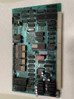
I'm trying to read and backup several UV erasable 2716 EPROM chips from a late 1970's/early 80's homebrew system.
my objectives are:
1, read the 4 chips on the CPU card to see if there is anything there still. i.e. SWTBUG, MIKBUK, 9BUG, (monitors)
2, archive anything that is on there just in case.
3, plug the chips in and try to boot the system.

Specific part numbers are :
Intel D2716
MOSTEK MK2716J-8

I have been trying to read with my cheap XGecu model T48 (tried various 2716 chip types and manufacturers - nothing reproducible/verifiable).
The only other rom reading device I have is the XTIDE card.

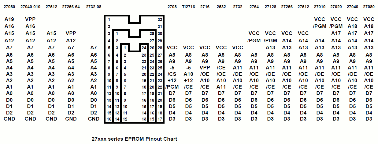
is there something fundamental I'm missing like the timing or voltage, NMOS/CMOS ?0D84F000-C417-4925-9350-B44119441740.jpeg
 
Reading a 2716 shouldn't be too bad, I do it with a TOP 3000 all the time.

It's programming them when you have to be extremely careful of programming voltage on these older/smaller ROMs.
 
Reading a 2716 shouldn't be too bad, I do it with a TOP 3000 all the time.

It's programming them when you have to be extremely careful of programming voltage on these older/smaller ROMs.
As pointed out above, you should at least be able to read a 2716 EPROM with the XGecu model T48.
You have tried this, but you say the result is "nothing reproducible/verifiable". Are you saying that the data you read from the 2716 is different every time you read from it, or something else?
 
Just for reference, there are some old Texas Instruments 2716 devices that require three (3) DC voltage rails (+5V, +12V and -5V).

You clearly don't have these devices - so it is not relevant to your particular problem - but these devices are out there... Avoid them like the plague!

The Intel D2716 is a fairly bog standard device.

Do you get the same results when you read the EPROM multiple times - or do you get different results every time?

Dave
 
Is it something daft (and easy done) that you have put it in the ZIF at the bottom rather than pin 1 at the top ? (I do it all the time with mine as the chip has to sit at the bottom of the ZIF)

I take it that 2716 is an option in the software ?
 
I was thinking more that the zif has more pins holes than the chip has and so the chip sits either right at the top or at the bottom. I think in yours it sits with pin 1 in the top most hole ? Whereas mine sits as low as it can go and I am forever putting chips in the wrong place.
 
With the Mostek chips the data read is different each time
It could be bad contacts so, as you already mentioned, sandpaper it a bit.

With the intel chip set as intel B2716 I just get zeros.
You mean D2716? If so, that's weird. Ran into many bad or partially erased EPROMs but never into one outputting zeros, certainly when normal data is to be expected.
 
1153191506083027242.gif
 
Although you should be able to read all four with any programmer which claims to support the 2716, if that's not working, do you have any small micro boards like an Arduino? You can use one of those to READ the code out of an EPROM, it's only the programming process which is rather specialised, needs weird voltages, and the exact process tends to vary from one manufacturer to the next. No such problem when reading them though.

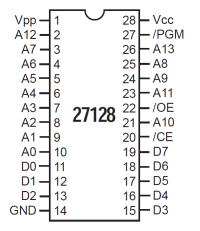
An Arduino UNO has just enough pins to drive A0-A9 (10 pins) and read the data bus (8 pins), with /CE and /OE assumed to be tied low to enable the chip for read. On a 2716 pin 21 (VPP) also needs to be tied to +5V when the chip is in read mode.
 
Last edited:
I was thinking more that the zif has more pins holes than the chip has and so the chip sits either right at the top or at the bottom. I think in yours it sits with pin 1 in the top most hole ? Whereas mine sits as low as it can go and I am forever putting chips in the wrong place.
6724E3CB-8D3F-4490-809A-3270B0AFA3B8.jpeg
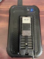
This is how its inserted, 2864 eeproms work perfectly like this for both read and write. So I’m fairly certain its in the right way.
 
I increased the Vcc setting to 5.5V - perhaps the usb port on my laptop isnt giving enough power?
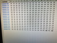
Now I get all 14s ! Except the last 4 bytes. I’m expecting the HCF program rom to be about 2 instructions long to cause the system to halt…
 
Although you should be able to read all four with any programmer which claims to support the 2716, if that's not working, do you have any small micro boards like an Arduino? You can use one of those to READ the code out of an EPROM, it's only the programming process which is rather specialised, needs weird voltages, and the exact process tends to vary from one manufacturer to the next. No such problem when reading them though.

An Arduino UNO has just enough pins to drive A0-A9 (10 pins) and read the data bus (8 pins), with /CE and /OE assumed to be tied low to enable the chip for read. On a 2716 pin 21 (VPP) also needs to be tied to +5V when the chip is in read mode.
I do have an unemployed arduino somewhere. If I cant get the XGecu T48 to work I could try and breadboard something…
 
I have (Or know of) several specific PROM / EPROM reader 'sketches' but the original one they were all derived from is this one here:-


Although written for an Arduino Mega which would be required for anything 'bigger' than a 2716, it could easily be tweaked to run on an UNO which has just enough general I/O pins to cope with a 2716.
 
I sometimes partially close the ZIF and then slide the chip sideways a back and forth. The chip's pins are only in contact with the ZIF with the pin's side edge. Any corrosion and contact may not be there.If this doesn't help, do you know anyone in your area with the a TL866 or a Wellon? I can read 2716's and TI 2516's on my 1st edition TL866A or on my Wellon 290. Worse case send the chips to someone and see if they can read them.
 
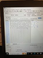
You’ll like this: the HCF chip is full of 14’s!!! and from the 6809 handbook "Opcodes $14, $15 and $CD all cause the CPU to stop functioning normally. One or more of these may be the HCF (Halt and Catch Fire) instruction. The HCF instruction was provided for manufacturing test purposes. Its causes the CPU to halt execution and enter a mode in which the Address lines are incrementally strobed. "
0E052ADE-EB50-4BC8-A7CC-F21D37A322F6.jpeg
 
Sorry, I got excited by a minor sucess.
I got one Mostek chip to read ok - so my reader can do it.
The combination of deoxit, sandpaper, and 5.5V Vcc gave me a readable chip.
The second chip is being more difficult, but the verify errors have been decreasing with continued chip cleaning. The chip only has a small block of code at the start,
And then its all FF, but with occasional errors. FF becomes FD so we can work out which pin needs cleaning.
072FF436-7809-4BE5-A80D-5332B8D88D9E.jpeg
 
You’ll like this: the HCF chip is full of 14’s!!!

Ugh, flashbacks to the time when I had code that went into the weeds and ran full speed into data, crashing into that test instruction. The watchdog ignored R/W because the hardware guy forgot to include it in the PAL, so the watchdog was well fed with reads, and the unattended device locked up. (That's when I learned that Roswell NM was like two hours from the nearest commercial airport.) It was made harder to debug by an ICE that used the same CPU for host and target operations. Fortunately Moto got a clue and on later chips (HC11 etc.) made it only work in special modes.

Also note that the 4 bytes at the end are probably the NMI and reset vectors. That chip really says it right on the tin, doesn't it?

The chip only has a small block of code at the start,

Here's what that disassembles to. It looks like it's initializing stuff and then might be putting test characters into some kind of video display. I don't think there would be anything else.
Code:
F800:   8EF86D                  LDX     #DF86D          ; initialization table
F803:   108EE6C0                LDY     #$E6C0          ; address of some I/O thing
F807:   8680                    LDA     #$80            ; set some register to $80
F809:   B7E740                  STA     $E740
F80C:   5F                      CLRB                    ; start with register zero
F80D:   A680            LF80D:  LDA     ,X+             ; get next init byte
F80F:   E7A4                    STB     ,Y              ; send register number
F811:   A721                    STA     1,Y             ; send data
F813:   5C                      INCB
F814:   C110                    CMPB    #$10
F816:   26F5                    BNE     LF80D           ; loop for 16 registers
F818:   4F                      CLRA                    ; set some register to $00
F819:   B7E6E1                  STA     $E6E1
F81C:   8620                    LDA     #$20
F81E:   8E4000                  LDX     #$4000
F821:   B7E6E0                  STA     $E6E0           ; set some register to $20
F824:   BFE6E2          LF824:  STX     $E6E2           ; store $40xx to $8000
F827:   3001                    LEAX    1,X
F829:   8C8000                  CMPX    #$8000
F82C:   26F6                    BNE     LF824
F82E:   CEF86F                  LDU     #DF86F          ; get DF6E
F831:   3704                    PULU    B
F833:   8620                    LDA     #$20            ; storing data of $20 to $7E
F835:   8E4000                  LDX     #$4000          ; for X = $4000 to $477F
F838:   108E0000                LDY     #$0000          ; for Y = $0000 to $00EF
F83C:   F7E6E1          LF83C:  STB     $E6E1
F83F:   B7E6E0                  STA     $E6E0
F842:   BFE632                  STX     $E632
F845:   E001                    SUBB    1,X
F847:   4C                      INCA
F848:   817F                    CMPA    #$7F
F84A:   2602                    BNE     LF84E
F84C:   8620                    LDA     #$20            ; if A=$7F, reset it to $20
F84E:   3121            LF84E:  LEAY    1,Y
F850:   108C00F0                CMPY    #$00F0
F854:   2608                    BNE     LF85E
F856:   108E0000                LDY     #$0000          ; if Y=$00F0, reset it to zero
F85A:   8620                    LDA     #$20            ; reset A to $20
F85C:   3704                    PULU    B               ; get next byte from before F86F
F85E:   8C4780          LF85E:  CMPX    #$4780
F861:   26D9                    BNE     LF83C           ; loop until X=4780
F863:   20FE            LF863:  BRA     LF863           ; infinite loop

F865:   00204080E001...         FCB     $00,$20,$40,$80,$E0,$01,$02,$03
F86D:   6350            DF86D:  FCB     $63,$50
F86F:   550819011818    DF86F:  FCB     $55,$08,$19,$01,$18,$18
F875:   000969090000...         FCB     $00,$09,$69,$09,$00,$00,$00,$00
F87D:   FFFFFF                  FCB     $FF,$FF,$FF
 
that would explain why the chip label reads “CRT”… again trust the tin.
How did you disassemble that so fast from a photo !
Really appreciate the effort.
I feel sufficiently confident to try the Intel chips again.
 
Back
Top