• Please review our updated Terms and Rules here

Recapping a Toshiba T3200, what caps?

Tom_of_Åland

Member
Joined
Dec 25, 2021
Messages
23
Location
Åland Islands
Hi,
Has anybody done a full recap on the T3200, and if so would you happen to have the details on what caps?
It would be so handy to order the caps in advance.

Thanks a lot!!
Tom
 
Apart from the line filer caps (RIFA or WIMA) in the psu and maybe the high voltage caps on the plasma panel. I don't think I've seen any capacitors fail in the T3200.
What makes you want to do a full recap?
 
Okay, I just thought that caps go bad with time. I had a dead T1000LE, made a full recap of about 15 small caps and it now works again.
 
Ohh yes, the T3200 doesn't have the same capacitor problems as some of the other Toshiba models.
Only other thing is the capacitors on the underside of the FDD drive. I've found those can cause it to not read disks.

From my experience these models do have capacitor issues:
Dynabook series (LE, SE, XE series): motherboard and display inverter
T1200: int PSU and LCD inverter
T1600: int PSU and LCD inverter
T3100sx: int PSU and plasma inverters
T3200sxc: display
T4400: int PSU
T6400: PSU and motherboard
T6600: PSU and motherboard

These don't:
T1000, T1100, T1100+, T2100, T3100, T3100e, T3200, T3200sx, T5100, T5200,

As a general rule most models with a removable battery have bad caps on the internal PSU.
 
I got a few t4400 laptops as parts machines. I hook them up to 21v and they draw 0 power. Even when I hit the power button, nothing. Are they toast or can the caps cause this?
 
I think people have got obsessed with global re-capping. Perhaps this "Disease" needs a name, maybe "The Global re-Capping disease" ?

It seems that when people get vintage computers and their power supplies, and they don't work, everybody jumps to the conclusion it is because the capacitors are defective in the power supply or on the computer board (perhaps we can thank Youtube videos for this).

While this could in fact be true in some cases, more often than not, it seems to throw professional fault finding techniques out the window.

Then what happens is, it appears that sometimes global re-capping works and sometimes it doesn't.

Mr. Spock from Star Trek would be disgusted with this but no, "disgusted" sounds like a Human emotion, so he would simply disapprove and tell you it was not logical. Thank God for his sense of reason.

There is a better way of course:

It doesn't involve "off the bat re-capping". Instead it involves logic (imagine that, you have to think for yourself to fix the problem).

The study of the schematic. How the circuit works. Then a series of tests on the circuit with meters and the scope. Then importantly formulating a theory on what has gone wrong. Then testing that theory with further tests and component checking. Then a targeted repair.
 
Last edited:
Also I could add that one saving grace with electrolytic caps (and there are not too many) is that they are readily tested in circuit with an ESR meter because the meter supplies such a low diagnostic voltage so as to not activate semiconductor junctions in the circuitry around the capacitor. Most other components are more difficult to acquire accurate test data on while in circuit.

There is no doubt though that if the pcb has the round surface mount electrolytic caps and is at an age where even one is showing signs of electrolyte leakage, they should all be replaced, because they are very destructive towards the pcb.
 
Thing is that professional fault finding takes a good amount of time to learn, and it requires a lot of expensive equipment in many cases. At the end of the day, recapping has a fair chance of fixing a lot of hardware as while it isn't the issue every time, it probably is the most common issue. It takes a lot less time and money to understand what a capacitor is, how to pick a proper replacement, and how to solder it in.
In certain cases, cap replacement would be pointless. It really depends on how whatever brand caps a piece of hardware have had age over time. In the case of these Toshibas, the list of models that need recapping above really always do, as they have ELNA Long Life caps inside, and that series from that time will all fail and leak, far worse than a SMD cap will because they're larger. There are other similar cases, like the Nichicon caps used on the Macintosh Classic and Classic II's analog boards, which also leak nearly 100% of the time and can't be trusted. Some brands have held up well though, like the light blue caps (not sure what brand) inside my Nan Tan FMA8100 laptop, which are all still fine. They're just as old, but I'm not worried about replacing them.

Point being, if you've got a dead piece of hardware and you don't have the advanced skills to fully debug the circuit, a recap can't hurt as long as you know the right type of caps to replace the originals with. I greatly respect those who can go look at a schematic, debug exactly what the circuit is doing with an oscilloscope, and then find that X chip or Y transistor has failed and replace it. We're not all that good though.
 
I agree that any electrolytic that is leaking electrolyte has to go asap. However at least with the option of in-circuit testing with the ESR meter, more targeted replacement can be done.

One thing about electrolytics, if you consider their applications (certainly in computers) their primary job is charge storage and power supply decoupling & filter applications. These circuits, in general, are not nearly as complicated as the logic circuitry in the computer. And even when electrolytics are used in signal coupling applications, in analog stages as you see them used in VDU's and audio cards etc, again the circuitry is not as complex as most of the computer's hard wired logic. In other words it is pretty easy to figure out if an electrolytic cap is doing its job or not.

It appears that there is some sort of myth going on about modern electros being better than older ones. Many early electros I have examined from the 70's era a still perfectly ok, especially if they were in low ripple current applications and signal coupling applications. But I have also seen some pretty poor new ones too (though these usually come from places other than Japan).

Even without the aid of a schematic, scope, understanding of a circuit, I think it is still better to replace when the result of a test indicates that you should. Every time an intervention is made on a pcb, there is always the chance of track damage, other thermal damage, unsuitable replacement part and part fitted in reverse etc. It can be hard enough to fix a fault, when there is just a single fault present. If other faults are introduced along the way, it can fall into chaos.

One strategy for global recapping, when it is done, is to re-check the board after each single capacitor replacement to see if the problem is resolved , or a new one introduced. But most people are not patient enough to do this and want to do the whole board in one go.
 
The study of the schematic.


That's the big one though. We are extremely lucky if we find a schematic on any of our equipment, even when it was new.


That aside,
I recapped the board and all the 1000uf's were leaking. Traces under all look good. Still no life from the module though, and no current draw when trying to turn it on. There are 2 fuses on the board and both are good so, I'm out of ideas.

I'm thinking recapping only works on these if they still show the power light but do not turn on.
The absence of the schematic doesn't have to stop you fixing it.

In a lot of cases if something is totally dead the cause can be easier to find. If the fuses are good, it could be something else like an open circuit inductor, failed fusible resistor or regulator. Or it could be that one of the power up/down sub-circuits (often done with a mosfet) has failed.

The idea is to study the trackwork and power distrubution on the board. With the board powered, check with the meter that all the IC's have voltage supplied to their power and ground pins is a good start. It is often obvious from the type of linear voltage regulators (if there are any), from their data sheets, what their input and output pins should be and those regulators can be checked. Generally the capcitors will have been springle along the varios power supply points. Sometimes the regulators are buck and other switching types to step the +5V down to 3.3V often with small dedicated IC or trannsistor sub circuits and you can check with the scope if these are operating and also get the data sheets if the devices have recognizable numbers.

When you say the "module" are you able to post any photos of it ? Are all the components visible on the pcb? If so its not too difficult to document the schematic from what is there. If potted, more tricky. If these modules have a Penchant for failure, it would be good to resolve the schematic, it helps other fix them too. I resolved the schematic, parts layout and design theory of the IBM5155 PSU and I'm sure that has helped other fix broken ones:

 
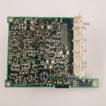
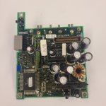
Here are photos of the front and back.

I have a reflow setup and most testing equipment up to a scope if you have questions.
 

Attachments

  • 20231219_225848.jpg
    20231219_225848.jpg
    675.8 KB · Views: 18
  • 20231219_223859.jpg
    20231219_223859.jpg
    1.3 MB · Views: 17
Looking at this board, it is likely a 4 layer type. Fairly conventional with most of the surface mount componentes on one side. The reason I say that is that I can see plated through holes that appear to pass through all layers, as they transmit light, but other smaller plated through holes do not.

See initially if you can document the power devices on it. And any of the IC's where you can make out the markings.

The presence of the Toroidal inductor suggests it has a switchmode regualtor. Therefore, the components in that area, specifically the IC's, you should be able to find their data sheets and application notes to help figure out the circuitry.
 
Last edited:
Also check the continuity of the white ceramic power resistors, it looks there are two of them. These types have a penchant for going open circuit.

When you removed the original capacitors, what method did you use to clean the pcb before fitting the new ones ?

It also looks like there are some custom hybrid modules used.
 
When you removed the original capacitors, what method did you use to clean the pcb before fitting the new ones ?
I used flux remover and then some isopropyl.


"It also looks like there are some custom hybrid modules used."

Can they be decapped or depotted?
 
If there was significant electrolyte leakage some interesting things can happen. It depends on the type of coating on the board.
The ones with the flat non- gloss type are more prone to the trouble. The electroyte invades it and it forms a leakage pathway between the tracks, as well as eating into the tracks too. It causes adjacent tracks to act like an electrolyic capacitor too.

A lot of the time the circuit won't malfunction as the leakage is in the many 100's of k range and it doesn't have much of an effect, say of it was just TTL logic, but if there are high impedance places in the circuitry it can cause serious problems. Some power standby control circuits using mosfets have resistances the the 1 meg range or higher and even any mild leakage in those can deactivate the circuit.

The electrolyte is highly ionic/polar and doesn't dissolve well at all with contact cleaners. It tends to be trapped in microscopic pores in the surface coating. It has to be leached out of the surface coating with water over time.

If you set up a thin stream of running hot water over the board surface from a tap, not so hot you cannot hold the board under it, and run that over the board for about 1 hour, it will leach out most of the electrolyte. Then after that wash the board with the contact cleaner to help displce the water then gently air dry it for another hour, only with warm air, nothing so hot that your skin couldn't put up with it. Also use a cue tip and the cleaner to clean the board surfaces where you can and inspect the fine tracks and vias for any corrosion damage. You might find a track has been eaten through, but hard to see without a lot of cleaning.

It is possible to unpot and replicate modules. But I'd consider that only if I could prove one was definitely defective with scope tests comparing it to a working unit and at least some partial schematics to help confirm it was defective.
 
I did some basic meter stuff on the mosfets and none of them appear shorted and only conduct between 2 of the pins in only one direction.

The big chip on the board is a microcontroller with prom. If it's hosed I'm out of luck.

The battery prongs take current when they are given voltage. I haven't tested to see what the current goes up to. I limited it at 0.1 a at 2.5v. Resistance comes back at 100 ohms.

The board itself draws zero milliamps to at least 2 decimal places. My fingers conduct better. The power button has no effect on this.

There is measurable resistance in the 100k range.

I figure if it was solely the microcontroller, there would still some life in the support circuitry.

All of the via's I see have traces . Not sure if that means its only 2 layer or not but that would be nice if true.
 
Ok, so I managed to get life, but Im just getting blink codes from the battery light. They are , variously depending on different factors hex. Bh, 15h, 7h
 
Back
Top