• Please review our updated Terms and Rules here

Replace your BA23 wiring if it is yellow..

MattisLind

Veteran Member
Joined
Sep 30, 2013
Messages
1,310
Location
Stockholm, Sweden
This has been discussed before I think.

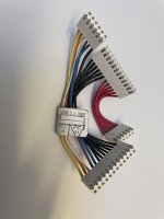
Opened up a VAXstation II/GPX in BA23 and the power harness wasn’t happy at all. In the previous BA23 I worked the power harness had white connectors and was in perfect shape.
IMG_4931.jpeg

So what should I do to replace it so it won’t catch fire? What is the proper connector. Some Molex KK 396 connector?
 
What you need is a TE MTA156 series connector.

For example the 18-pin part number is 4-640426-8 .

To assemble your own loom you'd need of course the pins, some 18AWG wire and a crimping tool as well

-Alon.
 
Not sure if I am missing something. Mouser says that 4-640426-8 is an IDC connector. I don't think I have any tools to actually press it together in a good way.
Not able to find the crimp terminals when searching on mouser. Checked TE pages as well.

On the other hand it seems that KK 396 and MTA 156 is compatible in that a KK 396 female will fit a MTA 156 male and vice versa: https://www.djerickson.com/molex-kk/
For KK 396 there are a big variety of crimp terminals and connector housings available.

If I remember correctly the replacement harness with white connectors wasn't IDC. So most likely they used Molex KK 396 then I guess. I am bit curious why the connector only burnt in the power supply end and not in the backplane end? Just one terminal had slight signs of heating. Of course it could have been an avalanche effect when terminals got heated up and resistance increased more load were put on the remaining terminals until it all broke down. Also will have a look on what the male connector in the PSU looks like. Perhaps need to replace it as well to make good contact in the future.

Not that I will run this machine 24/7 but it will be quite close to the max output with near max memory and a 8 plane VCB02.
Correct my mistake - the part number is for another type. MTA 156 is correct though. The series has its own crimp pins but indeed they appear obsolete even on the TE website...

-Alon.
 
I just checked the TE page it lists a SL-156 which looks reasonable as the crimp terminal type. Very similar to KK 396 at the first glance - but appears unavailable as well.
 
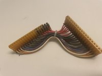
So I pulled out the new power harness from a BA23 and it looks like this:

IMG_4936.JPG

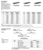
The connectors are marked AMP. Some more research show that these are SL156 connectors. They are to be found in the AMP-catalog from 1995. Page 3236 and onwards describe various variants of the MTA and SL connectors. MTA seems to be mostly IDC while SL is crimp. The male connector is the same. I pulled out one terminal in the harness and identified it as type B contact element. Maximum current is 6.5A.

The housing used are 640251-6 and 1-640251-2 while the contact elements are 350980-1 or 350980-2.

While I am quite confident that Molex KK 396 would fit I will get some of these housings and contact elements.
 
So I pulled out the new power harness from a BA23 and it looks like this:

View attachment 1299275

The connectors are marked AMP. Some more research show that these are SL156 connectors. They are to be found in the AMP-catalog from 1995. Page 3236 and onwards describe various variants of the MTA and SL connectors. MTA seems to be mostly IDC while SL is crimp. The male connector is the same. I pulled out one terminal in the harness and identified it as type B contact element. Maximum current is 6.5A.

The housing used are 640251-6 and 1-640251-2 while the contact elements are 350980-1 or 350980-2.

While I am quite confident that Molex KK 396 would fit I will get some of these housings and contact elements.
That's a much better harness implmentation than the original.
The Red wires are equal length. Better current balance. The same for the black wires.
The number one rule in parallel connections "All paths must be equal"
 
So I pulled out the new power harness from a BA23 and it looks like this:

View attachment 1299275

The connectors are marked AMP. Some more research show that these are SL156 connectors. They are to be found in the AMP-catalog from 1995. Page 3236 and onwards describe various variants of the MTA and SL connectors. MTA seems to be mostly IDC while SL is crimp. The male connector is the same. I pulled out one terminal in the harness and identified it as type B contact element. Maximum current is 6.5A.

The housing used are 640251-6 and 1-640251-2 while the contact elements are 350980-1 or 350980-2.

While I am quite confident that Molex KK 396 would fit I will get some of these housings and contact elements.
Do you know what the difference is between the two types of housings, and the two types of pins,is?
 
That's a much better harness implmentation than the original.
The Red wires are equal length. Better current balance. The same for the black wires.
The number one rule in parallel connections "All paths must be equal"
Although that's a good general rule, in this case the only real advantage appears to be cost savings due to only having to cut wires to a single length.

AWG18 wire has a resistance of 6.385Ω/1000ft(*). That's 532μΩ/inch. A 3 inch wire would have a resistance of 1.596mΩ and a 4 inch wire 2.128mΩ. The contact resistance of the connector is greater than that; it's rated at 4mΩ if I'm reading the specs properly(**). And that's best case. The failure in the original post was caused by increased contact resistance, not wire length resistance differences.

OK, so the BA23 power supply is rated for 40A@ +5V. There are 6 red wires, so each wire carries 1/6 of the load or 6.67A at full load (approximately - there are small differences due to wire length, of course). The difference in voltage drop in the two (3 inch vs. 4 inch) wires is therefore 3.55mV, which is .07% of the 5V being supplied. I have a hard time believing that is significant.

So maintaining low connector contact resistance - making that a periodic maintenance item - should be the takeaway here, and not worrying about small differences in wire lengths.

(*) http://hyperphysics.phy-astr.gsu.edu/hbase/Tables/wirega.html
(**) https://www.te.com/commerce/Documen...Lang=English&DocFormat=pdf&PartCntxt=770476-1
 
Do you know what the difference is between the two types of housings, and the two types of pins,is?

The difference between 640251-6 and 1-640251-2 is just the size. 6 vs 12 posistions. I think they used two smaller connectors to make it easier to remove and get into place. The force of the contact terminals would be quite high with 18 positions.

The difference 350980-1 and 350980-2 is the plating. "Brass, bright tin plated" vs "Brass, pre-tin plated". Not really sure what the difference are between the two and I cannot tell what sort they used in the original harness.
 
Although that's a good general rule, in this case the only real advantage appears to be cost savings due to only having to cut wires to a single length.

AWG18 wire has a resistance of 6.385Ω/1000ft(*). That's 532μΩ/inch. A 3 inch wire would have a resistance of 1.596mΩ and a 4 inch wire 2.128mΩ. The contact resistance of the connector is greater than that; it's rated at 4mΩ if I'm reading the specs properly(**). And that's best case. The failure in the original post was caused by increased contact resistance, not wire length resistance differences.

OK, so the BA23 power supply is rated for 40A@ +5V. There are 6 red wires, so each wire carries 1/6 of the load or 6.67A at full load (approximately - there are small differences due to wire length, of course). The difference in voltage drop in the two (3 inch vs. 4 inch) wires is therefore 3.55mV, which is .07% of the 5V being supplied. I have a hard time believing that is significant.

So maintaining low connector contact resistance - making that a periodic maintenance item - should be the takeaway here, and not worrying about small differences in wire lengths.

(*) http://hyperphysics.phy-astr.gsu.edu/hbase/Tables/wirega.html
(**) https://www.te.com/commerce/DocumentDelivery/DDEController?Action=srchrtrv&DocNm=108-1049-2&DocType=Specification Or Standard&DocLang=English&DocFormat=pdf&PartCntxt=770476-1
My H7864A supply is rated at 36A so 6A per +5V conductor in the harness. This is just below the 6.5A limit per connector element.

When checking for contact elements I saw that the SL156 could also use the "contact style C" which is rated at 10A. 770476-1 - costs about 20% more. But it doesn't seem to be the one they used in the DEC harness.

Screenshot 2025-04-15 at 08.40.34.png
 
Just to follow up on my last post: I should not have thought in terms of voltage drop. The six wires are connected at either end, so the voltage at the same end of each wire is equal. If I'm calculating correctly, it appears that the current balance is worse than I thought.

Assume AWG18 wires of lengths 3.0, 3.2, 3.4, 3.6, 3.8, and 4.0 inches. Resistance of wire plus connector (4mΩ) is then: 5.60mΩ, 5.70mΩ, 5.81mΩ, 5.92mΩ, 6.02mΩ, and 6.13mΩ.
The parallel resistance of these 6 wires (plus connector) is then 0.976mΩ. Let's use a 36A draw. This gives a voltage drop of about 35mV.

So the individual wires carry:
3.0 in: 6.279A
3.2 in: 6.162A
3.4 in: 6.049A
3.6 in: 5.940A
3.8 in: 5.835A
4.0 in: 5.734A

that's a difference of over half an amp between the shortest and longest lead, or nearly 10%. Power dissipated by connector resistance varies by about 20% (158mW for the 3.0 vs. 132mW for the 4.0). And that is starting to look significant. :oops:
 
The difference 350980-1 and 350980-2 is the plating. "Brass, bright tin plated" vs "Brass, pre-tin plated". Not really sure what the difference are between the two and I cannot tell what sort they used in the original harness.

As far as I can tell from some quick searching around on the net, bright tin plating includes some organic additives which causing the formation of fine grain structure deposits and a high degree of luster which is generally preferred for electrical contact applications, however if bright tin plating is soldered, the co-deposited organics in the deposit can burn. So maybe best for crimp terminals but not for solder terminals.

Pre-plating is when the plating occurs before the final machine forming steps occur, where the main benefit might be reduced production cost due to handling smaller numbers of larger pieces of material for plating than handling larger numbers of smaller parts. The downside is that there might be edges of the parts which are not plated if the parts are cut from larger pieces of material after the material has been plated.

Or course I could be wrong in the details here from what I found on the net.
 
Just to follow up on my last post: I should not have thought in terms of voltage drop. The six wires are connected at either end, so the voltage at the same end of each wire is equal. If I'm calculating correctly, it appears that the current balance is worse than I thought.

Assume AWG18 wires of lengths 3.0, 3.2, 3.4, 3.6, 3.8, and 4.0 inches. Resistance of wire plus connector (4mΩ) is then: 5.60mΩ, 5.70mΩ, 5.81mΩ, 5.92mΩ, 6.02mΩ, and 6.13mΩ.
The parallel resistance of these 6 wires (plus connector) is then 0.976mΩ. Let's use a 36A draw. This gives a voltage drop of about 35mV.

So the individual wires carry:
3.0 in: 6.279A
3.2 in: 6.162A
3.4 in: 6.049A
3.6 in: 5.940A
3.8 in: 5.835A
4.0 in: 5.734A

that's a difference of over half an amp between the shortest and longest lead, or nearly 10%. Power dissipated by connector resistance varies by about 20% (158mW for the 3.0 vs. 132mW for the 4.0). And that is starting to look significant. :oops:
Bonus points for checking your work!
When you look at the original harness the difference in wire length looks to be more than 1 inch used in your example. So the numbers look pretty bad.

The improved harness has another feature lacking in the original.
The connections between the wire and pin are much better in the improved harness.
Orignal is IDC. A fork that cuts the insulation and pinches the conductor. (I think it's two forks ) Very small contact area.
Improved: Full barrel crimp. Large contact area. Strain relief.
There were quite a few iterations of this before DEC got it right. The webbed IDC version burns at the IDC forks. The yellow one burns due to high contact resistance (IIRC, there was both an IDC and a crimp variant of the yellow one and neither were adequate). Be sure that the PSU and backplane connectors and their respective solder joints are OK, and replace / re-do as needed.

There's a whole long thread about this on DECUServe called "Burned up over BA23 fire".

At a DECUS Symposium, DEC was getting raked over the coals (of burned out BA23s) for making this a non-mandatory FCO. DEC said they didn't think it would affect many systems. One of the attendees came up to the microphone and gave her name and affiliation (one of the "Big 3" US automakers) and said that having an entire vehicle production line idled waiting for the FCO cost them a few million dollars in lost production.
 
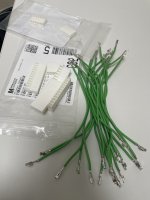
I've got the connector housings and crimp pins saved in a BOM on Mouser. I have 3 BA23 that I need to look at to see if any need a replacement harness. What's nice about Mouser for me is that they are in the DFW area and I can order on Sun-Thur and have the parts the next day for the most part.
 
I ordered my stuff from Mouser on Tuesday evening and the parcel guy from Fedex knocked on the door around lunch time on Thursday. 36 hours. Not that bad considering Stockholm is not next door exactly.

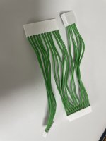
I tested the harness in the machine fully configured. No smoke, no fire. Have some trouble with the keyboard since it stops at A. Without VCB02 it goes down to 3 on the display in the back.
 
Thanks Henk for the offer! The total for two harneses was only around 18 euros and some time crimping the contacts, so not that much. Hopefully this research will be useful to others with same problem in the future.
 
Back
Top