• Please review our updated Terms and Rules here

Reviving old CGA monochrome graphics thread

RichCini

Veteran Member
Joined
Aug 6, 2005
Messages
598
Location
Long Island, NY
All --

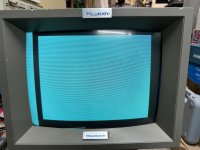
I have ongoing Lomas S-100 projects and one of them is getting Windows 1.04 running. The ColorMagic video board is CGA-compatible and generally runs anything I throw at it -- other than Windows. It would appear that the BIOS implementation is borked for the mode required (Mode 6, 640x200 B&W graphics). I ran the CGA Compatibility Tester and that passed (so the hardware is fine; bypasses the BIOS) but running a standard MS-DOS diagnostic (Check-It which uses INT10h) shows the same screen result as when trying to run Windows.

While searching, I came across this thread (CGA Composite Monochrome) which dealt more with fixing the look of monochrome characters on a composite monitor for a specific machine, but the issues are similar. So, my plan was to take the TSR template and see if I could create a BIOS replacement from it. I did search the Walnut Creek and SIMTEL archives for something already done, but there wasn't much there. If anyone has or knows of a utility that might work in this way, please let me know.

Thanks!

Rich
 
See attached picture. I'm trying to piece together where the fault is, but I think there's something dodgy in the BIOS implementation. I checked to see if the initialization bytes for the different modes were the same and they are (compared to the IBM BIOS and the "Generic" XT BIOS that's floating around). The Windows CGA driver seems to call INT10H only three times -- to enable video mode 6 or restore it to 3, and to check what mode it's in (al=15h). Otherwise, it draws right to RAM @ B800h.

FWIW, it seems that Windows works -- if I hit specific key sequences, I can get it to do things (like exit), but the screen isn't rendering properly.

The Lomas boards create a 2-board PC compatible in an S-100 footprint. The video board is billed as "CGA compatible". The CPU is compatible like the Tandy 2000 was -- the CPU is an 80186. I can run up to DOS 3.31 (PC-DOS 3.3 or Compaq DOS 3.31).

Rich
 

Attachments

  • IMG_4691.JPG
    IMG_4691.JPG
    2.4 MB · Views: 19
See attached picture. I'm trying to piece together where the fault is, but I think there's something dodgy in the BIOS implementation. I checked to see if the initialization bytes for the different modes were the same and they are (compared to the IBM BIOS and the "Generic" XT BIOS that's floating around). The Windows CGA driver seems to call INT10H only three times -- to enable video mode 6 or restore it to 3, and to check what mode it's in (al=15h). Otherwise, it draws right to RAM @ B800h.

FWIW, it seems that Windows works -- if I hit specific key sequences, I can get it to do things (like exit), but the screen isn't rendering properly.

The Lomas boards create a 2-board PC compatible in an S-100 footprint. The video board is billed as "CGA compatible". The CPU is compatible like the Tandy 2000 was -- the CPU is an 80186. I can run up to DOS 3.31 (PC-DOS 3.3 or Compaq DOS 3.31).

Rich
I don't know anything specific about that monitor, but I wondering if it has a "color killer" circuit adjustment. Most tv's of that era had "color killer" circuity and it just came to mind. Also, I know your monitor is not a tv.
 
It's an NEC Multisync rebadged as a Telerate terminal screen. I use this on my Tandy 2000. I've also tried this same setup with a scan converter (RGBtoHDMI; TexElec HDMI Upscaler) and I get the same result. I also pulled out an old Tandy CGA monitor (CM-4 I think) and I see the same blank screen, but without the artifact on the left side.
 
Last edited:
Huh. I dunno; it all Windows is doing is flipping it into graphics mode with BIOS calls and going to town it's kind of hard for me to think this is a CGA BIOS problem. It looks like it's making it *into* graphics mode at least (if it were wedged in text mode and Windows started drawing to screen memory you'd obviously have *much* different corruption... and it's also showing some single black dots on a few scanlines, which you couldn't get if it were in character mode anyway) and if that's the last time it touches the BIOS...

I googled around looking for the manual to that board, and I only found a rather short user pamphlet and a *very messy* schematic on DeRamp. Something I'm curious about: a real CGA card doesn't use MA13 from the CRTC; in terms of video addressing CGA uses this goofball system where the 16K it takes to display a 640x200 graphics grid is described in terms of 8K's worth of address lines (MA0-12) are combined with one row address as MA13, resulting in the every-other line interlacing we all know and love. I... genuinely cannot suss out how this Lomas board is replicating this behavior. It actually has MA13 hooked up (which implies this card is able to use all 32K of the installed video memory, instead of exhibiting the "roll-over" behavior a real CGA card exhibits if you write to locations above BBFFF), and I cannot find where it incorporates RA0 into driving the memory address lines. I see where it picks up RA0 and RA1 into a branch on their way to the character generator, but then I can't find them anywhere else. I assume they must feed into one of the PALs that they seem to have used to replace most of the discrete CGA circuitry, and either the RAx labels were redone into something else or they were cut off when the terrible scan was made... because obviously it must replicate this behavior or no PC graphics software would work properly, but...

... Anyway, where I was going with the above was I was wondering if it's possible the Windows driver (and perhaps Check-It's CGA check) might be effectively writing to the "other page" of CGA memory that this card has that a real CGA card doesn't, or, alternatively, the CRTC is landing with MA13 set high and it's actually displaying a page of memory from BC000-BCFFF? (On a real CGA card if MA13 is set high it wouldn't matter, it would still display B8000-BBFFF, because the address would just roll over.

It doesn't really feel like a monitor problem to me unless that Multisync monitor displays a white screen like that when it loses sync. If you really think it might be monitor related *somehow* I'd suggest putting a composite monitor on the output for that and verifying you see the same thing.
 
Thanks. I did a re-creation of the board, so it might be easier to read the KiCAD schematic on my Github page than the messy schematic from the original manual. The original used stacked lower-density memory sockets (i.e., stacked 8k chips) and I replaced them with two 62256 chips with A13 and A14 grounded (remember, MA0 = A1 because of the odd/even orientation. See the LS244's U57 and U58). MA13 acted as a chip select line. But, if there is a memory page thing, wouldn't there be corruption beyond a blank screen since it's picking up another address?

As to using a composite monitor, yes, I see a similar corruption on the composite output.

What I'd really like to try is another random program that uses Mode 6 that's NOT Windows and see if that has the same corruption.
 
Ooh, that’s a good idea. Let me see if I can find something to work with there. Not sure PC-DOS 3.3 comes with GW BASIC but maybe I'll try Compaq DOS 3.31 and see.
 
Last edited:
You can copy gwbasic from anywhere and use it. It's not bundled to a special dos version.
Yes. I found it. I just don't think it's on the PC-DOS 3.3 system disk by default. I made myself a "BASIC" disk image with different versions of BASIC/GWBASIC, so now I have something to play with. It's been a really long time since last using it...
 
MA13 acted as a chip select line.

So... I guess I should download your repo and load it into Kicad, because it doesn't look like you posted a PDF of the recreated version, but at least you've de-rotated and pieced together the original version, which helps some. It's really pretty awful... I love how it says "CS2", IE, inverted MA13, in pin "29" on the memory devices... when of course they were 28 pin devices. Presumably they had a flying wire to pin 20 on the top one?

Anyway...

But, if there is a memory page thing, wouldn't there be corruption beyond a blank screen since it's picking up another address?

Well, that's the thing, maybe? If this card really does have a linear 32K block instead of rolling over inside of 16K maybe the BIOS is clearing the whole 32K so when you land on the "wrong" page it's all white? (Except for those stray pixels, which might be considered "concerning".

I looked in the PAL equations you have in the repo and I guess I see where it processes RA0 and RA1 into a synthetic address line, but I'm not sure how this interacts with the MA13 supplied by the CRTC? Is there a manual for this card that describes what the card uses the extra video memory for? (Does it have a higher res/interlaced mode, or specifically mention multi-page graphics?)

Ooh, that’s a good idea. Let me see if I can find something to work with there.

If you get BASIC on there you can at least check to see what the paging behavior is. For laughs I wrote a little program to check to see if the real CGA rollover behavior is honored and tested it myself:

Code:
1 CLS
5 SCREEN 2
10 DEF SEG=&HB800
20 FOR X=0 TO &H7FFF
30 POKE X,INT(RND*255)
40 NEXT X

And... unearthed some interesting trivia. When I run this program on my Tandy 1000 EX (which I happen to have sitting out because I've been testing CGA monitor adapters) it replicates the expected authentic CGA behavior, IE, you'll see the screen fill up with random dots in an interlaced pattern, and then, after a short delay as it creeps through the remaining 384 bytes not used, it'll write through the whole screen again, same pattern. (IE, you'll see the random dots shift at random.) BUT, if I run this same program on my VGA-equipped 1000 HX you'll only get one round of random dots; the extra dots all get written to a hidden off-screen page. I actually verified that the random junk was there by adding the following lines to the program above:

Code:
50 END
100 OUT &H3D4, &HC
110 OUT &H3D5, &H20

The OUT statements in this addition change the base address in the CRTC to use "8192" as its starting address relative to the beginning of video memory instead of "0". When I "RUN 100" on the machine with real CGA the video display doesn't change *at all*; even though the CRTC is flipping the state of its MA13 address line it has no effect. When run on the VGA machine after the main program, however, I get a pristine field of the random dots. (And of course I have to blindly type "SCREEN 0" to get the CRTC reinitialized.

Of course I have *no idea* if this could be a problem for the Windows video driver. It seems a little suss because if what I'm seeing is how a standard VGA (and especially EGA) behaves, IE, they don't replicate the rollover, I would think someone would have mentioned that Windows 1.x didn't work on EGA or VGA cards in CGA mode, but... ?
 
Here's a link to the PDF; it's in the repro.

They used stacked sockets with extra pins that were offset into the space between the pins of the devices below. They did the same thing on the Thunder 186 board with the 36 DRAM chips. When I redid the CPU card, changing memory to regular SRAM saved 40 ICs.

I found another CGA test program on Vogons which is pretty thorough, testing through BIOS and direct to the hardware. All of the video modes work except 6. Mode 5 shows a little picture tearing occasionally but is very readable. I ran GW-BASIC and just typed SCREEN 2 and I got the same blank screen.

Running your test program also produces the same blank screen. I guess I can re-borrow the original Lomas board and see if what I'm seeing is an "edge case" from the memory substitution.
 
So "Screen 1" works but "Screen 2" doesn't? In terms of memory layout and CRTC settings those two modes should be identical.

What happens if you run my program with the following changes?
Code:
1 CLS
5 SCREEN 1
10 DEF SEG=&HB800
20 FOR X=0 TO &H1FFF
30 POKE X,INT(RND*255)
40 NEXT X
50 OUT &H3D8,30

This program sets the 320x200 4-color mode, fills the screen halfway with random color pixels, and then pokes the CGA mode control register to flip it into 640x200 monochrome, which I'm pretty sure should work to convert the non-white colored pixels into monochrome pixel patterns.

You mentioned that the card passed a "CGA compatibility tester"; I when I googled that it looked like the test mostly exercised edge-case features; are you certain the 640x200 output chain is working with *anything*? That's one of the "fun" things about the CGA card, it basically has three mostly separate pixel generation pipelines for the text modes and the two graphics modes.
 
When I run this, I get a full screen of random B&W pixels at what looks like 640x200 and then it goes into lala land with line 50. So in short, I'm not convinced Mode 6 works with anything.

I asked the person that I borrowed the original board from to test the modes using the program from Vogons and the above BASIC program and report back. It's quite possible it's (1) a design flaw in the original implementation or (2) a flaw in my conversion of the memory system. I've run the game Dig Dug which is probably 320x200/4 color.

Really appreciate you running through this with me.
 
Here's a link to the PDF; it's in the repro.

I'm reading your schematic, and I'm kind of feeling like you made a mistake with the handling of MA13? I wonder if it's possible there are knock-on effects here?

On the original with the stacked memory chips MA13 and its inverted evil twin were being used to choose between which 8K chip in the stack was selected. IE, this was not an "even-odd" situation, right? The plain version of it went to one chip and the inverted went to the other in the same stack, so depending on whether MA13 is high or not you're going to get the "first 8K" in the stack or the "second 8K". You eliminated the stacking, right, and just used two 32K chips? I see you have A13 and A14 tied to ground but you're still using MA13 as chip select, so with this setup you're only getting 16K (total, even odd, between the two chips, 8k each), and you're *only* getting that 16K when MA13 is "0". If MA13 were "1" you're essentially disconnecting the memory system.

MA13 is the buffered version of DA13, and DA13 is an output on the GAL that's doing magic with GA12/13 and RA0/1 from the CRT and several other signals, including GRAPH and CHG_DOTS. I haven't gone back to squint at the equations again, but are we certain that this card isn't doing something "clever" like using the second page of video memory (by setting MA13) when it's in Mode 6, or something like that? Because it looks to me you're going to get a mostly white screen if MA13 is ever high with your current setup. (Given that TTL inputs tend to float high, and floating is what you'll get if CS on the memory chips is a "1".)

I would humbly suggest yanking pins 2 and 20 on the memory chips out of their sockets, jumpering pin 2 (a12) to MA13, and grounding pin 20. That should make the memory system work similar to the original, I think?

EDIT: You could also break out the oscilloscope/logic analyzer and see if MA13 is high, IE, the chips select is muted, during the active video area when in mode 6. That'd be a smoking gun.

EDIT2: Note I'm not completely convinced by this theory, I don't know why they'd do something like that and if they didn't I'd *assume* the misconfiguration of the memory would only be an issue if you actually actively tried to use the second page, but... the manual doesn't seem to address what you'd use it for at all, so... (insert shrug emoji here).
 
Last edited:
The MA13 and its evil twin were for selecting the chip (upper or lower) in the even or odd stack, and each stack has it's own write gate. I'll try what you suggest later in the week when I get back to the bench. It's possible that I did muck it up (even after two years of re-development).

As I continue to thinking about it...you're probably spot-on with this. My friend ran the test program from Vogons and it did alternating bars at the right spacing. Grrr.
 
Last edited:
I’m pretty confident about the MA13 thing being “wrong” compared to the original board, in that how it’s set up is giving you less memory, but… I’m a little leery about proclaiming total victory?

Looked at the GAL code again and I’m *really* wondering now if this board was intended to support a 400 line mode or something like that as a variant of mode 6 (interlaced?) and something is mistakenly triggering it to go partially into that instead. (And when you’re in there it’s just trying to display the lines that are associated with the missing page?)

The reason I’m thinking like this is I’m peering at a real CGA schematic and unless I’m missing something the second row address line from the CRTC doesn’t have anything to do with addressing in graphics mode. (RA0, on the other hand does, essentially acting as MA13 in graphics mode.) The PAL equations for this board, on the other hand, relate the state of DA13 to both GA13 and RA1. Why would you involve RA1 here unless you were intending to do something like support 4-way interlacing? The address line A14 from the computer directly maps to A13, so memory writes to B8000 should only land there, so if the card is *intentionally* trying to render 200 lines from the (broken with the way MA13 is mapped) 16K of RAM at BC000 it’s doing it wrong.

So… I dunno. I definitely think you should fix the MA13 thing, but I also wonder if there’s a GAL equation that’s wrong somewhere…
 
Thanks. I plan on doing the MA13 patch either tomorrow or Thursday and will report back.

The GALs were reverse engineered by brute force because they’re secured. No equations were ever published so could there be something wrong there too? Sure. But I can’t imagine supporting an extended or odd mode. These came out near the end of the S100 platform for most people.
 
Back
Top